


—
17
—
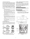
MOTORMASTER
SENSOR
LOCATION
HAIRPIN END
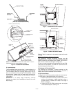
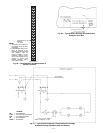
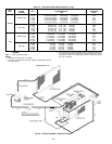
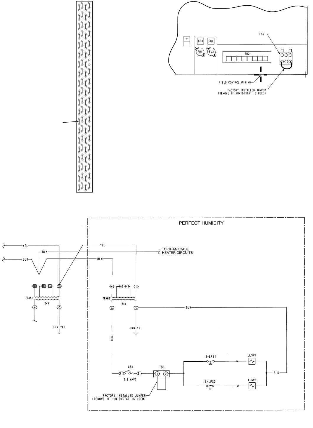
Fig. 26 — Motormaster® I and Motormaster III
Sensor Locations
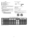
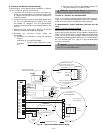
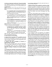
Fig. 28 — Typical Perfect Humidity Dehumidification
Package Control Box
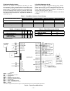
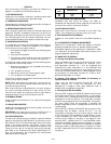
Fig. 27 — Typical Perfect Humidify™ Dehumidification Package
Humidistat Wiring Schematic (460V Unit Shown)
LEGEND
CB —
Circuit Breaker
LLSV —
Liquid Line Solenoid Valve
LPS —
Low-Pressure Switch
TB —
Terminal Block
TRAN —
Transformer
NOTES:
1. All sensors are located on
the eighth hairpin up from
the bottom.
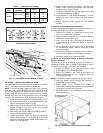
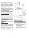
2. Field-installed tubing insu-
lation is required to be
installed over the TXV bulb
and capillary tube for
proper operation at low
ambients. Tubing insula-
tion is only required on the
portion of suction line
located between indoor
and outdoor section.