


56
11 NO PREVIOUS CODE – Stored codes
are erased after 72 hours. On RED LED
boards stored status codes can also be
erased whenever power (115V or 24V)
is interrupted. Run system through a
low-heat, high-heat, or cooling cycle to
check system.
12 BLOWER ON AFTER POWER UP –
(115V OR 24V) – Normal operation.
Blower runs for the selected blower off-
delay, if unit is powered up during a call
for heat (R-W/W1 closed) or when (R-
W/W1 opens) during the blower on-delay
period.
13 LIMIT CIRCUIT LOCKOUT – Lockout
occurs if the limit, draft safeguard, flame
rollout, or blocked vent switch* (if used)
is open longer than 3 minutes. Control will
auto-reset after 3 hours. See code 33.
14 IGNITION LOCKOUT – System failed to
ignite gas and prove flame in 4 attempts.
Control will auto-reset after 3 hours. See
status code 34.
21 GAS HEATING LOCKOUT– Turn off
power and wait 5 minutes to retry.
Check for:
- Stuck closed gas valve relay on
control.
- Miswire or short to gas valve wire.
22 ABNORMAL FLAME-PROVING SIGNAL
Flame is proved while gas valve is de-
energized. Inducer will run until fault is
cleared. Check for:
- Stuck open or leaky gas valve.
23 PRESSURE SWITCH DID NOT OPEN
Check for:
- Obstructed pressure tube.
- Pressure switch stuck closed.
24 SECONDARY VOLTAGE FUSE IS
OPEN Check for:
- Short circuit in secondary voltage
(24V) wiring including thermostat
leads. Disconnect thermostat leads
to isolate short circuit.
31 HIGH-HEAT PRESSURE SWITCH OR
RELAY DID NOT CLOSE OR
REOPENED - Check for:
- Control relay may be defective.
- Gas valve is miswired.
- See status code 32.
32 LOW-HEAT PRESSURE SWITCH DID
NOT CLOSE OR REOPENED – If open
longer than 5 minutes, inducer shuts off
for 15 minutes before retry. If opens
during blower on-delay period, blower
will come on for the selected blower off-
delay. Check for:
- Proper vent sizing.
- Low inducer voltage (115V).
- Low inlet gas pressure (if LGPS used).
- Inadequate combustion air supply.
- Disconnected or obstructed pressure
tubing.
- Defective inducer motor.
- Defective pressure switch.
- Excessive wind.
- Restricted vent.
33 LIMIT CIRCUIT FAULT– Indicates the
limit, draft safeguard, flame rollout, or
blocked vent shutoff switch* (if used) is
open.
Blower will run for 4 minutes or until
open switch remakes whichever is longer.
If open longer than 3 minutes, code
changes to lockout #13. If open less
than 3 min. status code #33 continues
to flash until blower shuts off. Flame
rollout switch and BVSS requires manual
reset. Check for:
- Dirty filter or restricted duct system.
- Loose blower wheel.
- Defective switch or connections.
- Defective blower motor or capacitor.
- Inadequate combustion air supply
(flame rollout switch open).
- Restricted vent.
- Proper vent sizing.
- Excessive wind.
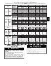
34 IGNITION PROVING FAILURE – If flame
is not sensed during the trial for ignition
period, the control will repeat the ignition
sequence 3 more times before lockout
#14 occurs. If flame signal is lost during
the blower on-delay period, blower will
come on for the selected blower off-delay.
Check the following items first before
proceeding to the next step.
- Gas valve turned off.
- Manual shut-off valve.
- Green/Yellow wire MUST be connected
to furnace sheet metal.
- Flame sensor must not be grounded.
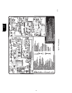
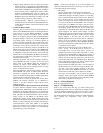
To determine whether the problem is in
the gas valve, igniter, or flame sensor
the system can be operated in the
component test mode to check the igniter.
First remove the R thermostat connection
from the control and initiate the
component test sequence. Does the
igniter glow orange/white by the end of
the 15 second warm-up period?
43 LOW-HEAT PRESSURE SWITCH OPEN
WHILE HIGH-HEAT PRESSURE
SWITCH IS CLOSED - Check for:
- Low-heat pressure switch stuck open.
- Disconnected or obstructed pressure
tube.
- Miswired pressure switches.
- Low inlet gas pressure (if LGPS used).
Unplug igniter harness from control and
initiate another component test sequence.
Check for 115V between pin 1 and
NEUTRAL-L2 on the control. Was 115V
present for the 15 second period?
Reconnect the R thermostat lead and set
thermostat to call for heat. Connect voltmeter
across gas valve connections. Does gas
valve receive 24V?
Does gas valve open and allow gas to flow?
Do the main burners ignite?
Do the main burners stay on?
Repeat call for heat and check flame sensor
current during trial for ignition period. Is the
DC microamps below 0.5?
Clean flame sensor with fine steel wool and
recheck current. Nominal current is 4.0 to
6.0 microamps.
Fixed.
45 CONTROL CIRCUITRY LOCKOUT Auto-
reset after 1 hour lockout due to:
- Flame circuit failure.
- Gas valve relay stuck open.
- Software check error.
Reset power to clear lockout. Replace
control if code repeats.
Replace furnace control.
Check for continuity in the harness and igniter.
Replace defective component.
Check connections. If OK, replace control.
Check that all gas valves are turned on.
Replace valve.
Check for:
- Inadequate flame carryover or rough
ignition.
- Low inlet gas pressure.
- Proper firing rate.
- Blocked or incorrect carry- over gap.
(.045” nominal)
Allow blower to come on and repeat test to
check for intermittent operation.
Check connections and retry. If current is
near typical value (4.0-6.0 nominal) and
burners will not stay on, repeat check in high-
heat. If burners will still not stay on replace
control. If burners operate in high-heat then
switch to low-heat, check manifold pressure.
If OK, check burner carryover and flame
sensor location.
NO
YES
YES
YES
YES
NO
YES
YES
YES
* Blocked vent shutoff switch used in Chimney Adapter Kit
NO
YES
NO
NO
NO
YES
NO
NO
Replace electrode.
Is current near typical value?
NO
Replace furnace control.
Will main burners ignite and stay on?
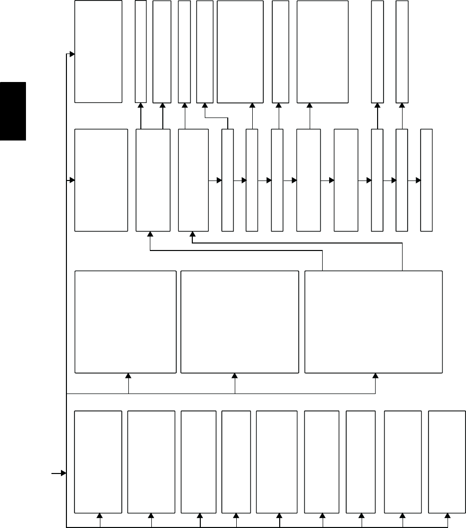
A05001
Fig. 63 -- Troubleshooting Guide 2-- Speed
312A