


15
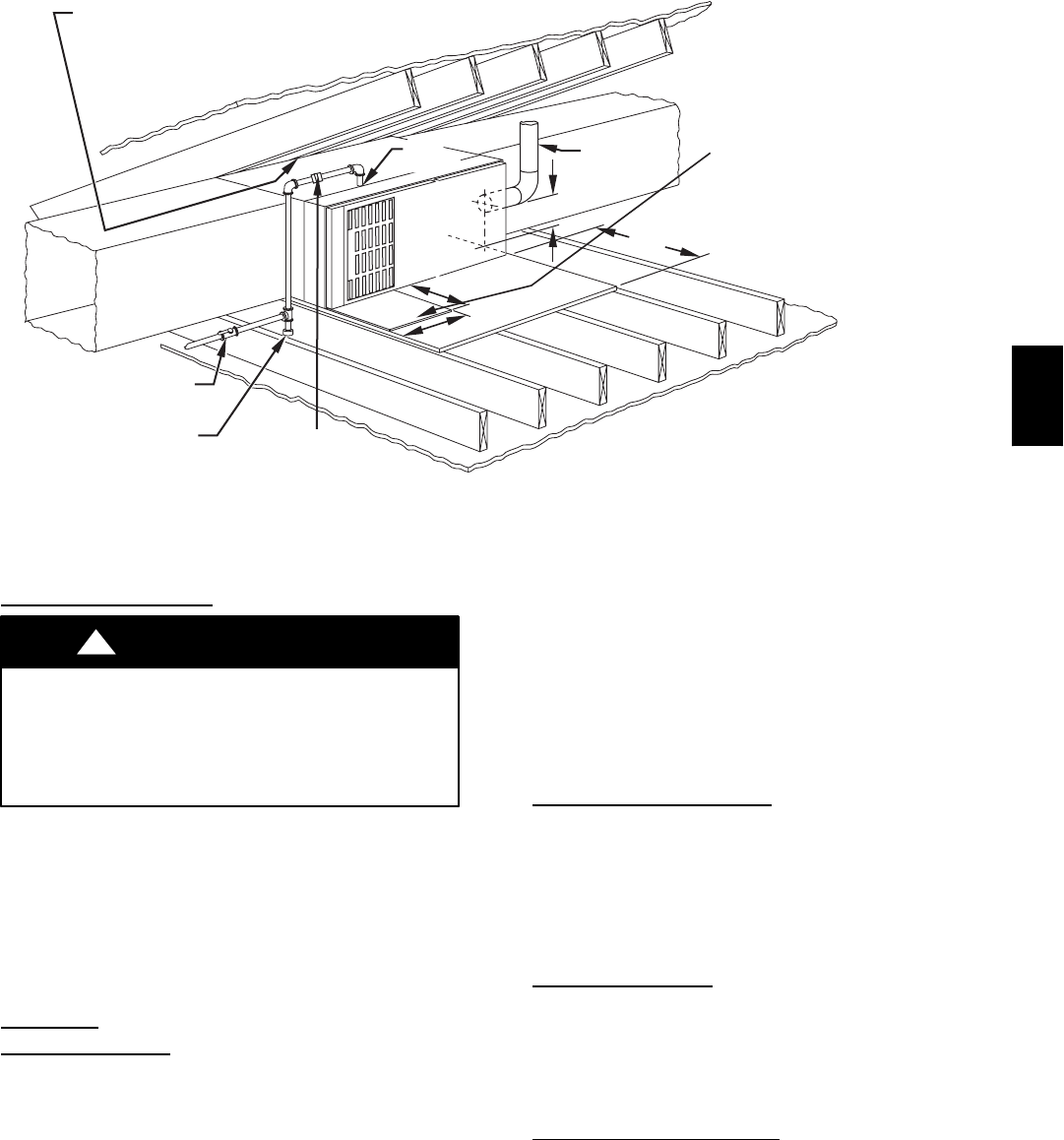
30-IN. MIN
WORK AREA
6″ MIN*
TYPE-B
VENT
17
3
/4
″
22
″
SHEET
METAL
SEDIMENT
TRAP
EQUIPMENT MANUAL
SHUT-OFF GAS VALVE
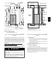
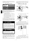
LINE CONTACT ONLY PERMISSIBLE BETWEEN
LINES FORMED BY INTERSECTIONS OF
THE TOP AND TWO SIDES OF THE FURNACE
JACKET AND BUILDING JOISTS,
STUDS, OR FRAMING.
GAS
ENTRY
17
3
/4
″ OVER ALL
4
3
/4
″ UNDER DOOR
1″ UNDER FURNACE
EXTEND OUT 12″ OUT
FROM FACE OF DOOR
* WHEN USED WITH
SINGLE WALL VENT
CONNECTIONS
UNION
A03177
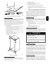
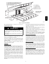
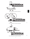
Fig. 17 -- Typical Attic Installation
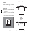
Not all horizontal furnaces are approved for side return air
connections. (See Fig. 20.)
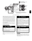
FILTER
ARRANGEMENT
CARBON MONOXIDE POISONING HAZARD
Failure to follow this warning could result in personal
injury, or death.
Never operate a furnace without a filter or with filter access
door removed.
!
WARNING
There are no provisions for an internal filter rack in these
furnaces. An external filter rack is required.
This furnace is shipped with a factory--supplied Media Filter
Cabinet. The Media Filter Cabinet uses either a factory--supplied
standard 1--inch filter or 4--inch wide Media Filter which can be
purchased separately.
Refer to the instructions supplied with Media Cabinet for
assembly and installation options.
AIR
DUCTS
General Requir
ements
The duct system should be designed and sized according to
accepted national standards such as those published by: Air
Conditioning Contractors Association (ACCA), Sheet Metal and
Air Conditioning Contractors National Association (SMACNA)
or American Society of Heating, Refrigerating and Air
Conditioning Engineers (ASHRAE) or consult The Air Systems
Design Guidelines reference tables available from your local
distributor. The duct system should be sized to handle the
required system design CFM at the design external static pressure.
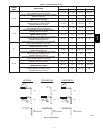
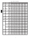
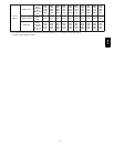
The furnace airflow rates are provided in Table 5--Air Delivery
CFM (With Filter).
When a furnace is installed so that the supply ducts carry air
circulated by the furnace to areas outside the space containing the
furnace, the return air shall also be handled by duct(s) sealed to
the furnace casing and terminating outside the space containing
the furnace.
Secure ductwork with proper fasteners for type of ductwork used.
Seal supply-- and return--duct connections to furnace with code
approved tape or duct sealer.
NOTE: Flexible connections should be used between ductwork
and furnace to prevent transmission of vibration.
Ductwork passing through unconditioned space should be
insulated to enhance system performance. When air conditioning
is used, a vapor barrier is recommended.
Maintain a 1--in. clearance from combustible materials to supply
air ductwork for a distance of 36 in. horizontally from the
furnace. See NFPA 90B or local code for further requirements.
Ductwork Acoustical Tr
eatment
NOTE: Metal duct systems that do not have a 90_ elbow and 10
ft of main duct to the first branch take--off may require internal
acoustical lining. As an alternative, fibrous ductwork may be used
if constructed and installed in accordance with the latest edition of
SMACNA construction standard on fibrous glass ducts. Both
acoustical lining and fibrous ductwork shall comply with NFPA
90B as tested by UL Standard 181 for Class 1 Rigid air ducts.
Supply Air
Connections
For a furnace not equipped with a cooling coil, the outlet duct
shall be provided with a removable access panel. This opening
shall be accessible when the furnace is installed and shall be of
such a size that the heat exchanger can be viewed for possible
openings using light assistance or a probe can be inserted for
sampling the air stream. The cover attachment shall prevent leaks.
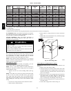
Upflow and Horizontal
Furnaces
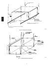
Connect supply--air duct to flanges on furnace supply--air outlet.
Bend flange upward to 90_ with wide duct pliers. (See Fig. 14.)
The supply--air duct must be connected to ONLY the furnace
supply--outlet--air duct flanges or air conditioning coil casing
(when used). DO NOT cut main furnace casing side to attach
supply air duct, humidifier, or other accessories. All accessories
MUST be connected to duct external to furnace main casing.
312A