


18
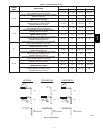
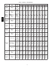
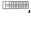
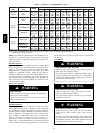
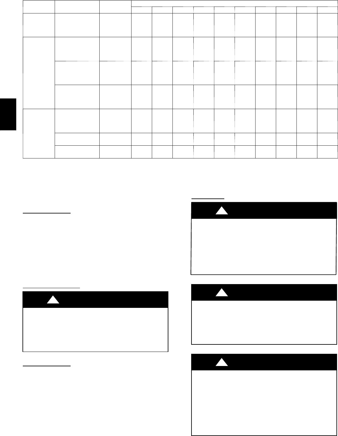
Table 5 -- Air Delivery -- CFM (W ith Filter)* (Cont.)
FURNACE
SIZE
RETURN---AIR
INLET
SPEED
EXTERNAL STATIC PRESSURE (IN. WC)
0.1 0.2 0.3 0.4 0.5 0.6 0.7 0.8 0.9 1.0
135---16 /
048135
Bottom
or
Side(s)
High
M ed --- Hi g h
M ed --- L ow
Low
2090
1790
1545
1325
2010
1755
1525
1320
1930
1705
1500
1295
1835
1640
1450
1265
1710
1550
1380
1210
1590
1465
1315
1150
1470
1360
1215
995
1335
1210
1005
865
1025
945
855
745
835
785
670
540
135---22 /
066135
Bottom
Only
High
M ed --- Hi g h
M ed --- L ow
Low
2485
2195
1880
1640
2400
2150
1850
1635
2310
2090
1820
1615
2215
2000
1780
1585
2110
1920
1715
1530
2000
1825
1635
1465
1880
1720
1540
1370
1725
1565
1415
1255
1535
1405
1290
1150
1355
1255
1160
1040
Bottom Sides
or
1 Side & Bottom
High
M ed --- Hi g h
M ed --- L ow
Low
--- ---
2180
1880
1640
--- ---
2145
1850
1635
2385
2060
1820
1615
2305
2010
1780
1585
2195
1945
1715
1530
2085
1865
1635
1465
1960
1765
1540
1370
1825
1660
1415
1255
1670
1515
1290
1150
1465
1325
1160
1040
1SideOnly
High
M ed --- Hi g h
M ed --- L ow
Low
2320
2125
1845
1640
2250
2065
1825
1620
2155
1995
1765
1580
2055
1910
1710
1540
1970
1815
1650
1485
1855
1710
1570
1410
1725
1610
1475
1330
1600
1490
1370
1220
1450
1340
1240
1080
1280
1175
1100
960
155---20 /
060155
Bottom Only
High
M ed --- Hi g h
M ed --- L ow
Low
2465
2115
1800
1570
2430
2105
1790
1565
2375
2075
1770
1550
2305
2030
1735
1525
2230
1980
1695
1495
2110
1910
1640
1445
2000
1830
1570
1370
1865
1725
1465
1270
1725
1590
1345
1175
1545
1425
1225
1070
Both Sides Or 1
Side & Bottom
High
M ed --- Hi g h
--- ---
2155
--- ---
2135
2375
2095
2285
2040
2200
1975
2105
1895
1995
1790
1870
1685
1730
1550
1570
1400
1SideOnly
High
M ed --- Hi g h
--- ---
2140
--- ---
2095
2260
2040
2180
1975
2085
1890
1975
1810
1865
1705
1740
1595
1605
1480
1455
1325
*A filter is required for each return--- air inlet. Airflow performance included 1--- in. washable filter media such as contained in factory---authorized accessory filter
rack. To determine airflow performance without this filter, assume an additional 0.1 in. wc available external static pressure.
------ Indicates unstable operating conditions.
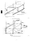
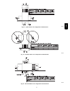
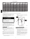
NOTE: For horizontal applications, the top--most flange may be
bent past 90_ to allow the evaporator coil to hang on the flange
temporarily while the remaining attachment and sealing of the
coil are performed.
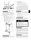
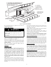
Downflow
Furnaces
Connect supply--air duct to supply--air outlet on furnace. Bend
flange inward past 90_ with wide duct pliers. (See Fig. 14.) The
supply--air duct must be connected to ONLY the furnace
supplyoutlet or air conditioning coil casing (when used). When
installed on combustible material, supply--air duct must be
connected to ONLY the accessory subbase, KGASB0201ALL, or
a factory approved air conditioning coil casing. DO NOT cut
main furnace casing to attach supply side air duct, humidifier, or
other accessories. All accessories MUST be connected to duct
external to furnace casing.
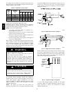
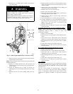
Return Air
Connections
FIRE HAZARD
Failure to follow this warning could cause personal injury,
death and/or property damage.
Never connect return--air ducts to the back of the furnace.
Follow instructions below.
!
WARNING
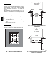
Downflow Furnaces
The return--air duct must be connected to return--air opening
(bottom inlet) as shown in Fig. 1. DO NOT cut into casing sides
(left or right). Side opening is permitted for only upflow and most
horizontal furnaces. Bypass humidifier connections should be
made at ductwork or coil casing sides exterior to furnace. (See
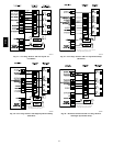
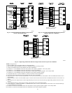
Fig. 19.) Upflow and Horizontal Furnaces The return--air duct
must be connected to bottom, sides (left or right), or a
combination of bottom and side(s) of main furnace casing as
shown in Fig. 1. Bypass humidifier may be attached into unused
return air side of the furnace casing. (See Fig. 18 and 20.) Not all
horizontal furnaces are approved for side return air connections.
(See Fig. 20.)
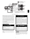
GAS
PIPING
FIRE OR EXPLOSION HAZARD
Failure to follow this warning could result in personal
injury, death, and/or property damage.
Never purge a gas line into a combustion chamber. Never
test for gas leaks with an open flame. Use a commercially
available soap solution made specifically for the detection
of leaks to check all connections.
!
WARNING
FIRE OR EXPLOSION HAZARD
Failure to follow this warning could result in personal
injury, death, and/or property damage.
Use proper length of pipe to avoid stress on gas control
manifold and a gas leak.
!
WARNING
FIRE OR EXPLOSION HAZARD
Failure to protect gas valve inlet from water and debris
could result in death, personal injury and/or property
damage.
Gas valve inlet and/or inlet pipe must remain capped until
gas supply line is permanently installed to protect the valve
from moisture and debris. Also, install a sediment trap in the
gas supply piping at the inlet to the gas valve.
!
WARNING
312A