


37
a. Turn gas valve ON/OFF switch to OFF.
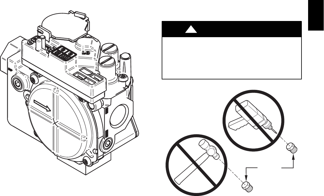
b. Remove manifold pressure tap plug from gas valve.
c. Connect a water column manometer or similar device to
manifold pressure tap.
d. Turn gas valve ON/OFF switch to ON.
e. Move setup switch LHT (SW--1) on furnace control to
ON position to lock furnace in low--heat operation. (See
Fig. 34 and Table 10.)
f. Manually close blower door switch.
g. Jumper R and W/W1 thermostat connections on control
to start furnace. (See Fig. 34.)
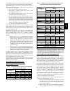
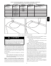
h. Remove regulator adjustment cap from low--heat gas
valve pressure regulators. (See Fig. 54.) Turn low--heat
adjusting screw (3/16 in. or smaller flat tipped
screwdriver) counterclockwise (out) to decrease input
rate or clockwise (in) to increase input rate.
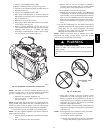
A06667
Fig. 54 -- Redundant Automatic Gas Control Valve
NOTE: DO NOT set low--heat manifold pressure less than
1.4--in wc or more than 1.7--in. wc for natural gas. If manifold
pressure is outside this range, change main burner orifices.
i. Install low--heat regulator adjustment cap.
j. Leave manometer or similar device connected and
proceed to Step 4.
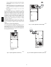
NOTE: If orifice hole appears damaged or it is suspected to have
been re--drilled, check orifice hole with a numbered drill bit of
correct size. Never re--drill an orifice. A burr--free and squarely
aligned orifice hole is essential for proper flame characteristics.
4. Verify natural gas low--heat input rate by clocking meter.
NOTE: Gas valve regulator adjustment caps must be in place for
proper input to be clocked.
a. Turn off all other gas appliances and pilots served by the
meter.
b. Run for 3 minutes in low--heat operation.
c. Measure time (in sec) for gas meter to complete 1
revolution and note reading. The 2 or 5 cubic feet dial
provides a more accurate measurement of gas flow.
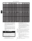
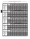
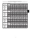
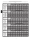
d. Refer to Table 12 for cubic ft of gas per hr.
e. Multiply gas rate cu ft/hr by heating value (Btuh/cu ft)
to obtain input. If clocked rate does not match required
input from Step 1, increase manifold pressure to increase
input or decrease manifold pressure to decrease input.
Repeat steps b through e until correct low heat input is
achieved. Re--install low--heat regulator seal cap on gas
valve.
5. Set low--heat temperature rise. The furnace must operate
within the temperature rise ranges specified on the furnace
rating plate. Do not exceed temperature rise ranges
specified on unit rating plate for high--and low--heat.
Determine the temperature rise as follows:
NOTE: Blower access door must be installed when taking
temperature rise reading. Leaving blower access door off will
result in incorrect temperature measurements.
ELECTRICAL SHOCK HAZARD
Failure to follow this warning could result in personal
injury or death.
Disconnect 115--v electrical power before changing speed
tap.
!
WARNING
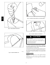
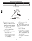
BURNER
ORIFICE
A93059
Fig. 55 -- Orifice Hole
a. Verify unit is running in low heat per Step 4. Place
thermometers in return and supply ducts as close to
furnace as possible. Be sure thermometers do not see
radiant heat from heat exchangers. Radiant heat affects
temperature rise readings. This practice is particularly
important with straight--run ducts.
b. When thermometer readings stabilize, subtract return--air
temperaturefromsupply--airtemperatureto determineair
temperature rise.
NOTE: If the temperature rise is outside this range, first check:
(1.) Gas input for low heat operation.
(2.) Derate for altitude if applicable.
(3.) Return and supply ducts for excessive restrictions
causing static pressures greater than 0.50--in. wc.
312A