


3
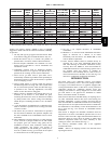
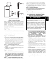
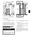
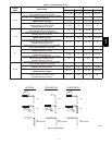
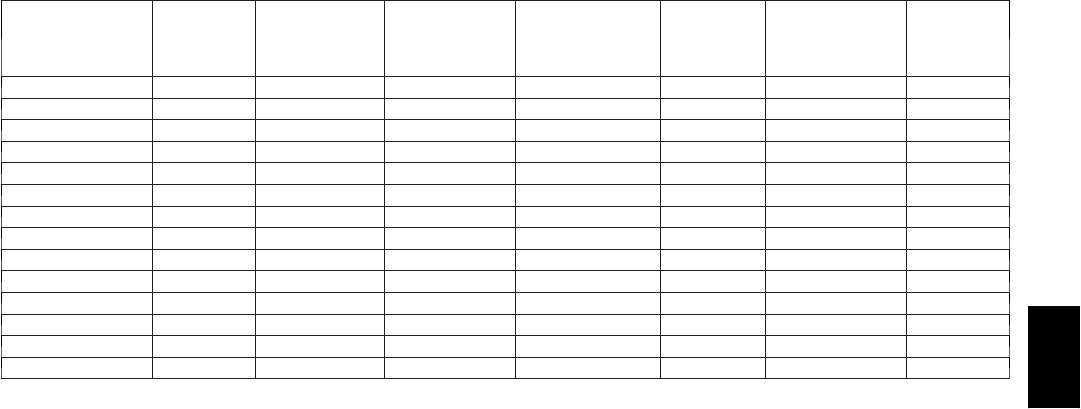
Table 1 – Dimensions (In.)
FURNACE SIZE
A
CABINET
WIDTH
(IN.)
D
SUPPLY---AIR
WIDTH (IN.)
E
RETURN---AIR
WIDTH (IN.)
F
C.L. TOP AND
BOTTOM FLUE
COLLAR (IN.)
FLUE
COLLAR*
(IN.)
SHIP WT. (LB)
FILTER
MEDIA
CABINET
SIZE (IN.)
045---08/024045 14---3/16 12---9/16 12---11/16 9---5/16 4 116 16
045---12/036045 14---3/16 12---9/16 12---11/16 9---5/16 4 119 16
070---08/024070 14---3/16 12---9/16 12---11/16 9---5/16 4 120 16
070---12/036070 14---3/16 12---9/16 12---11/16 9---5/16 4 124 16
070---16/048070 17---1/2 15---7/8 16 11---9/16 4 138 16
090---14/042090 17---1/2 15---7/8 16 11---9/16 4 136 16
090---16/048090 21 19---3/8 19---1/2 13---5/16 4 151 20
090---20/060090 21 19---3/8 19---1/2 13---5/16 4 156 20
110---12/036110 17---1/2 15---7/8 16 11---9/16 4 144 16
110---16/048110 21 19---3/8 19---1/2 13---5/16 4 158 20
110---22/066110 21 19---3/8 19---1/2 13---5/16 4 163 20
135---16/048135 21 19---3/8 19---1/2 13---5/16 4† 163 20
135---22/066135 24---1/2 22---7/8 23 15---1/16 4† 174 24
155---20/060155 24---1/2 22---7/8 23 15---1/16 4† 181 24
* 5” or 6” vent connector may be required in some cases.
{ 135 and 155 size furnaces require five---inch or larger vents. Use a 4---5 or 4---6 inch vent adapter between furnace and vent connector.
product and property damage. NOTE is used to highlight
suggestions which will result in enhanced installation, reliability,
or operation.
1. Use only with type of gas approved for this furnace. Refer
to the furnace rating plate 2. Install this furnace only in a
2. Install this furnace only in a location and position as
specified in the “Location” section of these instructions.
3. Provide adequate combustion and ventilation air to the
furnace space as specified in “Air for Combustion and
Ventilation” section.
4. Combustion products must be discharged outdoors.
Connect this furnace to an approved vent system only, as
specified in the “Venting” section of these instructions.
5. Never test for gas leaks with an open flame. Use a
commercially available soap solution made specifically for
the detection of leaks to check all connections, as specified
in the “Gas Piping” section.
6. Always install furnace to operate within the furnace’s
intended temperature--rise range with a duct system which
has an external static pressure within the allowable range,
as specified in the “Start--Up, Adjustments, and Safety
Check” section. See furnace rating plate.
7. When a furnace is installed so that supply ducts carry air
circulated by the furnace to areas outside the space
containing the furnace, the return air shall also be handled
by duct(s) sealed to the furnace casing and terminating
outside the space containing the furnace. See “Air Ducts”
section.
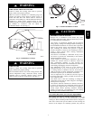
8. A gas--fired furnace for installation in a residential garage
must be installed as specified in the warning box in the
“Location” section.
9. The furnace may be used for construction heat provided
that the furnace installation and operation complies with
the first CAUTION in the LOCATION section of these
instructions.
10. These Multipoise Gas--Fired Furnaces are CSA (formerly
A.G.A. and C.G.A.) design--certified for use with natural
and propane gases (see furnace rating plate) and for
installation in alcoves, attics, basements, closets, utility
rooms, crawlspaces, and garages. The furnace is
factory--shipped for use with natural gas. A CSA (A.G.A.
and C.G.A.) listed accessory gas conversion kit is required
to convert furnace for use with propane gas.
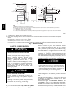
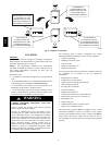
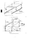
11. See Fig. 2 for required clearances to combustible
construction.
12. Maintain a 1--in. clearance from combustible materials to
supply air ductwork for a distance of 36 inches
horizontally from the furnace. See NFPA 90B or local
code for further requirements.
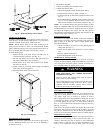
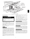
13. These furnaces SHALL NOT be installed directly on
carpeting, tile, or any other combustible material other
than wood flooring. In downflow installations, factory
accessory floor base MUST be used when installed on
combustible materials and wood flooring. Special base is
not required when this furnace is installed on
manufacturer’s Coil Assembly Part No. CD5 or CK5, or
when Coil Box Part No. KCAKC is used. See Fig. 2 for
clearance to combustible construction information.
INTRODUCTION
The Series 120/C 4--way multipoise Category I fan--assisted
furnace is CSA (formerly A.A.A.. and C.G.A.) design--certified.
A Category I fan--assisted furnace is an appliance equipped with
an integral mechanical means to either draw or force products of
combustion through the combustion chamber and/or heat
exchanger. The furnace is factory--shipped for use with natural
gas. This furnace is not approved for installation in mobile
homes, recreational vehicles, or outdoors.
These furnaces shall not be installed directly on carpeting, tile, or
any other combustible material other than wood flooring. For
downflow installations, a factory accessory floor base must be
used when installed on combustible materials and wood flooring.
This special base is not required when this furnace is installed on
the manufacturer’s coil assembly, or when the manufacturer’s coil
box is used. See Fig. 2 for clearance to combustible material
information.
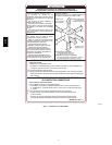
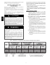
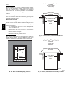
This furnace is designed for minimum continuous return--air
temperature of 60_F db or intermittent operation down to 55_F
db such as when used with a night setback thermostat. Return--air
temperature must not exceed 80_F db. Failure to follow these
return--air temperature limits may affect reliability of heat
exchangers, motors, and controls. (See Fig. 3.)
For accessory installation details, refer to the applicable
instruction literature.
NOTE: Remove all shipping brackets and materials before
operating the furnace.
312A