


35
In Canada: Per section 8.24.2 of the CAN/CSA--B149.1--05,
any listed mechanical venter may be used, when approved by the
authority having jurisdiction.
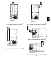
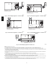
Select the listed mechanical venter to match the Btuh input of the
furnace being vented. Follow all manufacturers installation
requirements for venting and termination included with the listed
mechanical venter.
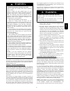
START--UP, ADJUSTMENT, AND SAFETY
CHECK
Step 1 — General
FIRE HAZARD
Failure to follow this warning could result in personal
injury, death and/or property damage.
This furnace is equipped with manual reset limit switches in
the gas control area. The switches open and shut off power
to the gas valve if a flame roll--out or overheating condition
occurs in the gas control area. DO NOT bypass the
switches. Correct problem before resetting the switches.
!
WARNING
1. Maintain 115--v wiring and ground. Improper polarity will
result in rapid flashing LED and no furnace operation.
2. Make thermostat wire connections at the 24--v terminal
block on the furnace control. Failure to make proper
connections will result in improper operation. (See Fig.
24.)
3. Gas supply pressure to the furnace must be greater than
4.5--in. wc (0.16 psig ) but not exceed 14--in. wc (0.5
psig).
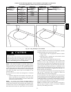
CUT HAZARD
Failure to follow this caution may result in personal injury.
Sheet metal parts may have sharp edges or burrs. Use care
and wear appropriate protective clothing, safety glasses and
gloves when handling parts and servicing furnaces.
CAUTION
!
4. Check all manual--reset switches for continuity.
5. Install blower compartment door. Door must be in place to
operate furnace.
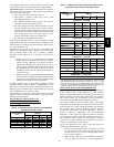
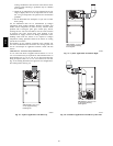
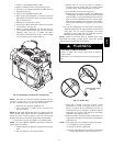
6. Setup switch descriptions The 2 stage furnace has DIP
switches used to select thermostat staging and blower off
delay timings. For switch locations on Furnace control
board, See Fig. 34 and 58.
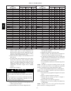
7. Setup switch descriptions -- See Table 10.
Step 2 — Start--Up Procedures
FIRE AND EXPLOSION HAZARD
Failure to follow this warning could cause personal injury,
death and/or property damage.
Never purge a gas line into a combustion chamber. Never
use matches, candles, flame, or other sources of ignition for
the purpose of checking leakage. Use a soap--and--water
solution to check for leakage.
!
WARNING
1. Purge gas lines after all connections have been made.
2. Check gas lines for leaks.
ELECTRICAL SHOCK HAZARD
Failure to follow this warning could result in personal
injury, or death. Blower access door switch opens 115--v
power to control. No component operation can occur unless
switch is closed. Caution must be taken when manually
closing this switch for service purposes.
!
WARNING
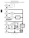
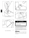
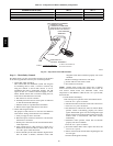
3. To Begin Component Self--Test:
Remove blower access door. Disconnect the thermostat R
lead from furnace control board. Manually close blower
door switch. Short (jumper) the COM--24v terminal on
control to the TEST/TWIN 3/16--inch quick--connect
terminal on control until the LED goes out (approximately
2 sec). Gas valve and humidifier will not be turned on.
Remove jumper from terminals. (See Fig. 34 and Table
10.)
NOTE: The furnace control allows all components, except the
gas valve, to be run for short period of time. This feature helps
diagnose a system problem in case of a component failure.
Component test feature will not operate if any thermostat signal is
present at the control.
Refer to service label attached to furnace or See Fig. 57.
Component test sequence is as follows:
a. LED will display previous status code 4 times.
b. Inducer motor starts on high--speed and continues to run
until Step g of component test sequence.
c. Hot surface igniter is energized for 15 sec., then off.
d. Blower motor operates on LO--HEAT speed for 10 sec.
e. Blower motor operates on HI--HEAT speed for 10 sec.
f. Blower motor operates on COOL speed for 10 sec.
g. Inducer motor goes to low--speed for 10 sec., then stops.
h. Reconnect R lead to furnace control board, remove tape
from blower door switch and re--install blower door.
4. Operate furnace per instruction on inner door.
5. Verify furnace shut down by lowering thermostat setting
below room temperature.
6. Verify furnace restarts by raising thermostat setting above
room temperature.
312A