


20
Gas piping must be installed in accordance with national and
local codes. Refer to current edition of NFGC in the U.S. and the
CAN/CSA--B149.1--05 in Canada.
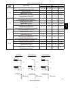
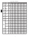
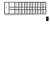
Table 6 – Maximum Capacity of Pipe*
NOMINAL
IRON
PIPE
SIZE
(IN.)
INTERNAL
DIAMETER
(IN.)
LENGTH OF PIPE (FT)
10 20 30 40 50
1/2 0.622 175 120 97 82 73
3/4 0.824 360 250 200 170 151
1 1.049 680 465 375 320 285
1 --- 1/ 4 1.380 1400 950 770 660 580
1 --- 1/ 2 1.610 2100 1460 1180 990 900
* Cubic ft of natural gas per hr for gas pressures of 0.5 psig (14---in. wc)
or less and a pressure drop of 0.5---in wc (based on a 0.60 specific gravity
gas). Ref: Table 12.2 ANSI Z223---2006/NFPA 54---2006.
Installations must be made in accordance with all authorities
having jurisdiction. If possible, the gas supply line should be a
separate line running directly from meter to furnace.
NOTE: In the state of Massachusetts:
1. Gas supply connections MUST be performed by a
licensed plumber or gas fitter.
2. When flexible connectors are used, the maximum length
shall not exceed 36 inches (915 mm).
3. When lever handle type manual equipment shutoff valves
are used, they shall be T--handle valves.
4. The use of copper tubing for gas piping is NOT approved
by the state of Massachusetts.
Refer to Table 6 for recommended gas pipe sizing. Risers must be
used to connect to furnace and to meter. Support all gas piping
with appropriate straps, hangers, etc. Use a minimum of 1 hanger
every 6 ft Joint compound (pipe dope) should be applied
sparingly and only to male threads of joints. Pipe dope must be
resistant to the action of propane gas.
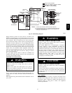
FIRE OR EXPLOSION HAZARD
Failure to follow this warning could result in personal
injury, death, and/or property damage.
If local codes allow the use of a flexible gas appliance
connector, always use a new listed connector. Do not use a
connector which has previously served another gas
appliance. Black iron pipe shall be installed at the furnace
gas control valve and extend a minimum of 2 in. outside the
furnace.
!
WARNING
FURNACE DAMAGE HAZARD
Failure to follow this caution may result in furnace damage.
Connect gas pipe to furnace using a backup wrench to
avoid damaging gas controls and burner misalignment.
CAUTION
!
An accessible manual equipment shutoff valve MUST be
installed external to furnace casing and within 6 ft of furnace. A
1/8--in. NPT plugged tapping, accessible for test gauge
connection, MUST be installed immediately upstream of gas
supply connection to furnace and downstream of manual
equipment shutoff valve.
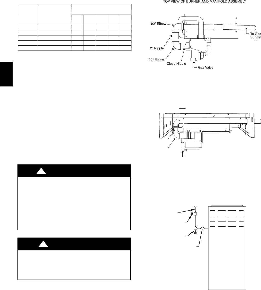
NOTE: The furnace gas control valve inlet pressure tap
connection is suitable to use as test gauge connection providing
test pressure DOES NOT exceed maximum 0.5 psig (14--in. wc)
stated on gas control valve. (See Fig. 54.) Some installations
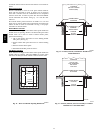
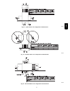
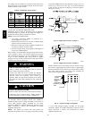
require gas entry on right side of furnace (as viewed in upflow).
(See Fig. 21 and 22.)
A05028
Fig. 21 -- Right Side Gas Entry Example 1
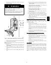
90° Elbow
2" Nipple
Street Elbow
Gas Valve
A02327
Fig. 22 -- Right Side Gas Entry Example 2
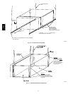
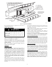
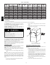
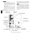
Install a sediment trap in riser leading to furnace as shown in Fig.
23. Connect a capped nipple into lower end of tee. Capped nipple
should extend below level of furnace gas controls. Place a ground
joint union between furnace gas control valve manifold and
exterior manual equipment gas shutoff valve.
UNION
SEDIMENT
TRAP
MANUAL
SHUTOFF
VALVE
(REQUIRED
GAS
SUPPLY
A02035
Fig. 23 -- Typical Gas Pipe Arrangement
A 1/8--in. NPT plugged tapping, accessible for test gauge
connection, MUST be installed immediately upstream of gas
supply connection to furnace and downstream of manual
equipment shutoff valve.
312A