


49
CLEANING AND/OR REPLACING AIR FILTER
The air filter arrangement will vary depending on the application.
NOTE: If the filter has an airflow direction arrow, the arrow
must point towards the blower.
CUT HAZARD
Failure to follow this caution may result in personal injury.
Sheet metal parts may have sharp edges or burrs. Use care
and wear appropriate protective clothing, safety glasses and
gloves when handling parts and servicing furnaces.
CAUTION
!
Media cabinet filter procedures:
NOTE: Media Cabinet is included with two--stage furnace.
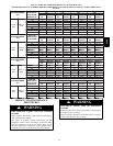
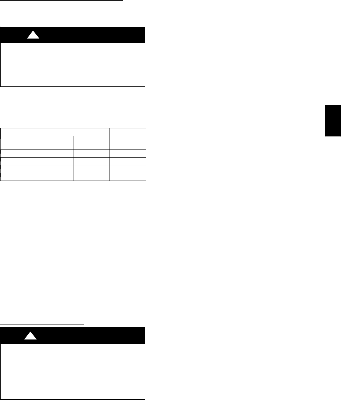
Table 17 – Filter size information (in.)
FURNACE
CASING
WIDTH
FILTER SIZE
FILTER TYPE
Side Return
Bottom Re-
turn
14---1/2 16 X 25 X 1 14 X 25 X 1 Cleanable*
17---1/2 16 X 25 X 1 16 X 25 X 1 Cleanable*
21 16 X 25 X 1 20 X 25 X 1 Cleanable*
24 16 X 25 X 1 24 X 25 X 1 Cleanable*
*Recommended
1. Turn off electrical supply to furnace before removing filter
access door.
2. Remove filter cabinet door.
3. Slide filter out of cabinet.
4. If equipped with permanent, washable 1--in filter, clean
filter by spraying cold tap water through filter in opposite
direction of airflow. Rinse filter and let dry. Oiling or
coating of the filter is not recommended. See Table 17 for
size information.
5. If equipped with factory--specified disposable media filter,
replace only with media filter having the same part
number and size. For expandable replacement media, refer
to the instructions included with the replacement media. If
equipped with accessory KGAFR0301ALL external filter
rack. See Table 17.
6. Slide filter into cabinet.
7. Replace filter cabinet door.
8. Turn on electrical supply to furnace.
BLOWER MOTOR AND
WHEEL
ELECTRICAL SHOCK HAZARD
Failure to follow this warning could result in personal
injury or death.
Blower access door switch opens 115--v power to control.
No component operation can occur unless switch is closed.
Caution must be taken when manually closing this switch
for service purposes.
!
WARNING
NOTE: The blower wheel should not be dropped or bent as
balance will be affected.
The following steps should be performed by a qualified
service agency .
To ensure long life and high efficiency, clean accumulated dirt
and grease from blower wheel and motor annually.
The inducer and blower motors are pre--lubricated and require no
additional lubrication. These motors can be identified by the
absence of oil ports on each end of the motor.
Clean blower motor and wheel as follows:
1. Turn off electrical supply to furnace.
2. Loosen the thumbscrew from outer door and remove outer
door.
3. For downflow or horizontal furnaces having vent pipes
within the furnace that pass in front of the blower access
door:
a. Disconnect vent connector from furnace vent elbow.
b. Disconnect and remove short piece of vent pipe from
within furnace.
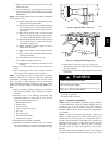
4. Remove 2 screws from blower access door and remove
blower access door.
5. Disconnect blower leads from furnace control. Record
wire color and location for reassembly. All other factory
wires can be left connected, but field thermostat
connections may need to be disconnected depending on
their length and routing.
6. Remove 2 screws holding control box to blower shelf.
7. Hang control box from front of furnace casing and away
from blower compartment.
8. Remove 2 screws holding blower assembly to blower
deck and slide blower assembly out of furnace.
9. Clean blower wheel and motor using a vacuum with soft
brush attachment. Blower wheel blades may be cleaned
with a small paint or flux brush. Do not remove or disturb
balance weights (clips) on blower wheel blades.
10. Vacuum any loose dust from blower housing, wheel and
motor.
11. If a greasy residue is present on blower wheel, remove
wheel from the blower housing and wash it with an
appropriate degreaser. To remove wheel:
NOTE: Before disassembly, mark blower mounting arms, motor,
and blower housing so motor and each arm is positioned at the
same location during reassembly.
a. Disconnectcapacitorwires(if equipped)and ground wire
attached to blower housing.
b. Remove screws securing cutoff plate and remove cutoff
plate from housing.
c. Loosen set screw holding blower wheel on motor shaft
(160+/--20 in.--lb. when reassembling).
d. Removeboltsholding motor to blower housing and slide
motor outof wheel (40+/--10in.--lb.whenreassembling).
e. Remove blower wheel from housing.
f. Clean wheel and housing.
12. Reassemble motor and blower by reversing steps 11e,
through 11a. Be sure to reattach ground wire to the blower
housing.
13. Verify that blower wheel is centered in blower housing
and set screw contacts the flat portion of the motor shaft.
Loosen set screw on blower wheel and reposition if
necessary.
14. Spin the blower wheel by hand to verify that the wheel
does not rub on the housing.
15. Reinstall blower assembly in furnace.
312A