


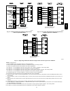
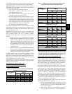
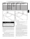
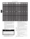
33
Caution!! For the following applications, use the minimum vertical heights as specified below.
For all other applications, follow exclusively the National Fuel Gas Code
FURNACE
ORIENT ATION
VENT ORIENTA-
TION
FURNACE IN-
PUT(BTUH/HR)
MINIMUM VENT
DIAMETER (IN.)*
MINIMUM VERTICAL VENT
HEIGHT (FT)**
Downflow
Vent elbow left, then
up Fig. 40
154,000
132,000
110,000(036/---12 only)
5 12
Horizontal Left
Vent elbow right,
then up Fig. 43
154,000
132,000
5 7
Horizontal Left
Vent Elbow up Fig.
44
154,000
132,000
5 7
Horizontal Left
Vent elbow right Fig.
45
154,000 5 7
Downflow
Vent elbow up then
left Fig. 38
110,000 (036/---12 only) 5 10
Downflow
Vent elbow up, then
right Fig. 41
110,000 (036/---12 only) 5 10
NOTE: All vent configurations must also meet National Fuel Gas Code venting requirements NFGC. *4 in. inside casing or vent guard **Including 4 in. vent
section(s)
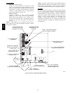
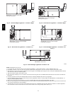
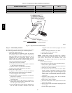
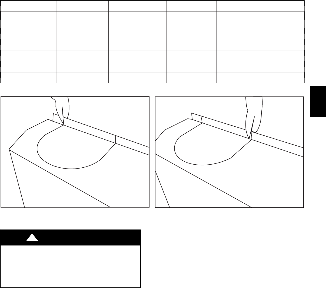
A04127
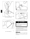
Fig. 49 -- Using Tin Snips to Cut Tie Points
CUT HAZARD
Failure to follow this caution may result in personal injury.
Sheet metal parts may have sharp edges or burrs. Use care
and wear appropriate protective clothing, safety glasses and
gloves when handling parts and servicing furnaces.
CAUTION
!
NOTE: Vent connector length for connector sizing starts at
furnace vent elbow. The 4 inch vent elbow is shipped for upflow
configuration and may be rotated for other positions. Remove the
3 screws that secure vent elbow to furnace, rotate furnace vent
elbow to position desired, re--install screws. The factory--supplied
vent elbow does NOT count as part of the number of vent
connector elbows.
The vent connector can exit the door through one of 5 locations
on the door.
1. Attach the single wall vent connector to the furnace vent
elbow, and fasten the vent connector to the vent elbow
with at least two field--supplied, corrosion--resistant, sheet
metal screws located 180_ apart.
NOTE: An accessory flue extension KGAFE0112UPH is
available to extend from the furnace elbow to outside the furnace
casing. If flue extension is used, fasten the flue extension to the
vent elbow with at least two field--supplied, corrosion--resistant,
sheet metal screws located 180_ apart. Fasten the vent connector
to the flue extension with at least two field--supplied, corrosion
resistant sheet metal screws located 180_ apart.
2. Vent the furnace with the appropriate connector as shown
in Fig. 36--48.
3. Orient the door to determine the correct location of the
door knockout to be removed.
4. Remove the correct U--shaped knockout in door.
NOTE: A number of techniques can be used to remove these
knockouts as seen in Fig. 49 through 53. The knockout in the
bottom of the door is unique due to its flanging and is more easily
removed by first cutting the two tie points at the edge of the door,
using aviation--type tin snips. (See Fig. 49.) A sharp blow to the
rounded end of the knockout (See Fig. 50.) will separate more tie
points and allow the knockout to be pulled loose. (See Fig. 51.)
Remove all burrs any sharp edges.
For the rectangular J--box knockout, use tin snips along the door
edge and use a sharp blow with a hammer to remove the
knockout. Remove any burrs and sharp edges.
For the knockouts in the other locations on the door (top and
sides), tin snips can also be used along the door edges; however,
the preferred method is to use a hammer and screwdriver to strike
a sharp blow (See Fig. 52.) directly to the knockout tie points or
use a hammer in the upper left corner of the desired knockout.
(See Fig. 53.) Remove any burrs and sharp edges.
NOTE: If a knockout does not come out after two sharp blows,
pull and snip as needed to remove the knockout. Additional
blows may cause damage to the door.
312A