


28 en | Installation MIC612 Thermal Camera
F.01U.249.416 | 2.0 | 2012.09 Installation Manual Bosch Security Systems, Inc.
29. After wiring is complete, connect the power supply to the power source.
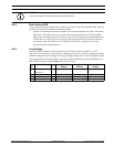
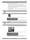
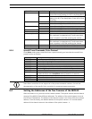
30. Verify that the following LEDs are lit:
31. Re-attach the enclosure lid and tighten the four (4) captive screws on the cover door to
ensure that the enclosure is watertight.
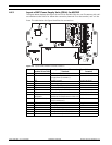
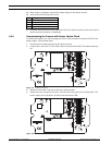
4.4.5 Commissioning the Camera with Heater Option Fitted
To enable the heaters, you must change two links on the printed circuit board (PCB) of the
power supply. Follow these steps:
1. Disconnect the power supply from the power source.
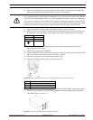
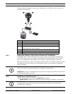
2. Locate Link 1 and Link 2 on the PCB, next to terminal block HD6. The default setting is
0V.
Figure 4.9 PCB links set to 0V
3. Break the two solder links and remove any excess solder.
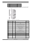
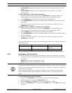
4. Solder the links, using TCW link wire, from the left hand pads to the middle pads. The
power supply will now deliver 18 VAC to terminal block HD6.
Figure 4.10 PCB links set to 18V
LED Description
LED 2 18 VAC power on to camera
LED 4 Power on for optional heater
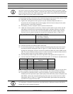
LED 3 18 VAC power on camera
LED 5 Power on for optional heater