


MIC612 Thermal Camera Installation | en 25
Bosch Security Systems, Inc. Installation Manual F.01U.249.416 | 2.0 | 2012.09
8. Remove the blanking plug. Install suitable (metal) conduit in place of the blanking plug.
Secure the conduit as recommended by the conduit manufacturer.
9. Prepare the power cable as need, then feed the cable into the enclosure.
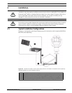
10. Connect the Live and Neutral cores to the correct screw terminals on terminal block HD1
as identified in the table below and printed on the PCB. Observe polarity and voltage.
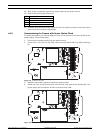
11. Remove the brass nut and copper washer from the earth termination post (item 3,
Figure 4.6); set these aside.
12. Remove the ring terminal (supplied).
13. Insert the earth core from the mains cord (item 2, Figure 4.6) into the crimp portion (size
M6, UL-certified) of the ring terminal and crimp it in place.
14. Place the ring terminal onto the earth termination post.
15. Replace the copper washer. Secure with the brass nut.
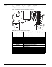
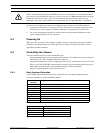
Figure 4.6 Mains input with shield removed, showing terminal block HD1 before wiring
16. Replace the internal shield, taking care to avoid pinching the cables. Tighten the screws.
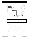
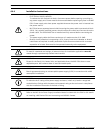
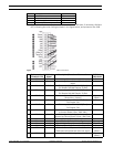
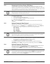
17. Feed the unconnected end of the shielded composite cable through the top-right M16
cable gland (item 2, Figure 4.7).
Figure 4.7 MIC PSU Enclosure, with cable glands identified
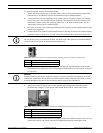
CAUTION!
Only installations with conduit meet UL standards. If you choose to use a power cord without
conduit (not recommended), fit the 1/2 in. NPT cable gland (supplied) in place of the blanking
plug. Note: It is easier to fit the power cord through the cable gland outside of the enclosure,
and then attach the gland to the enclosure. Ensure that the cable glands have sufficient room
to allow for the cables to enter (approximately 60 mm on either side of the enclosure).
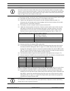
PCB Marking Description
LLive
N Neutral
Earth / Ground
Number Description
1 Earth core cable to enclosure lid
2 Earth core cable to power supply PCB
3 Earth termination post