


18 en | Installation MIC612 Thermal Camera
F.01U.249.416 | 2.0 | 2012.09 Installation Manual Bosch Security Systems, Inc.
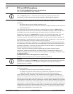
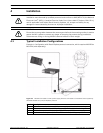
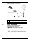
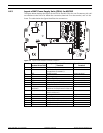
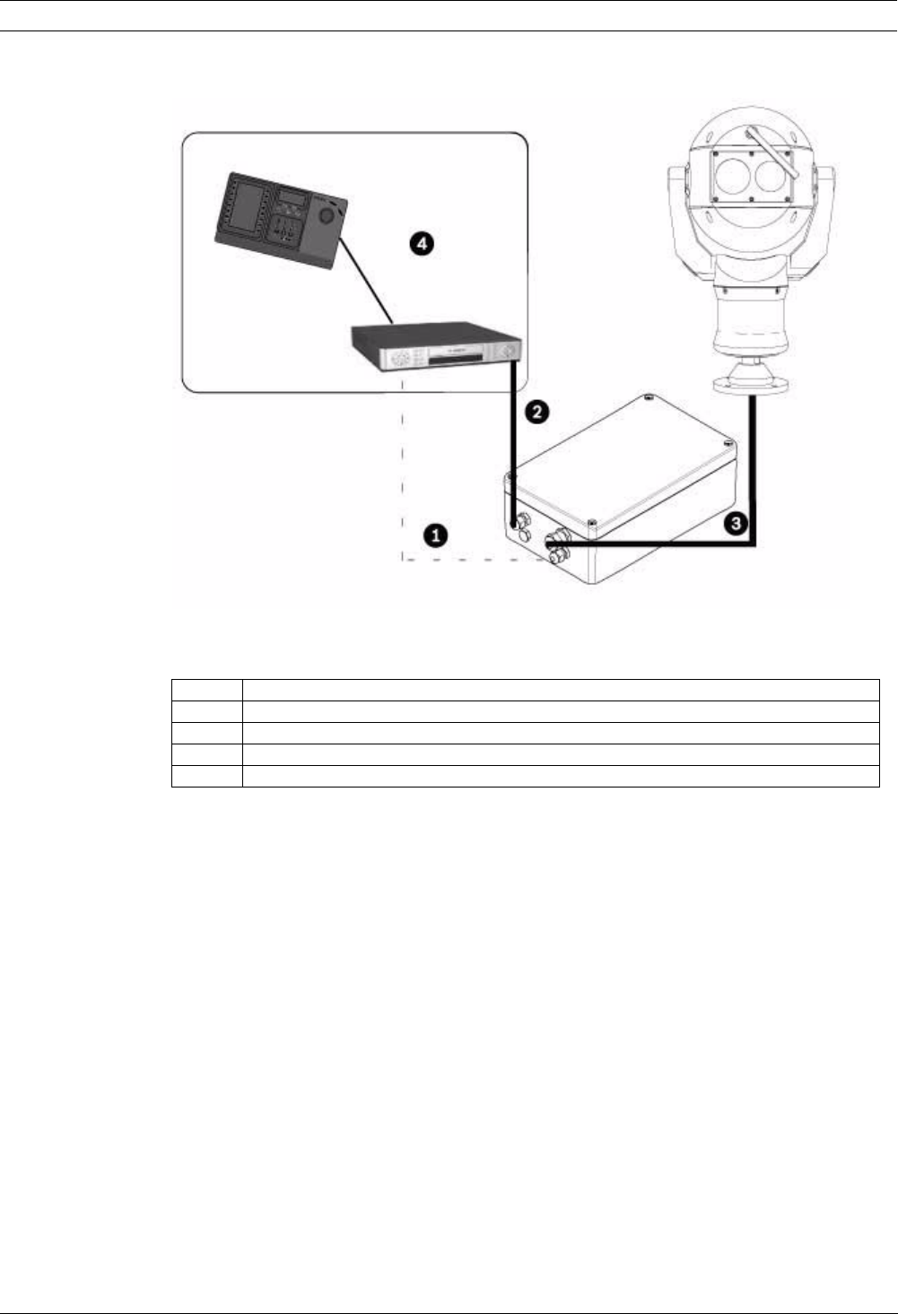
Example 2: Configuration with RS-485 protocol connection
Figure 4.2 MIC612 connected to a MIC power supply, which is connected to a head-end control system by
RS-485.
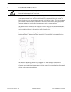
4.2 Overview of Installation Steps
Follow these steps in sequence to install the MIC612 camera.
Note: Depending on your desired mounting position and location, as well as your chosen
accessories, you may not need to complete every step.
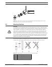
1. Mount the camera. See Section 4.3 Mounting the Camera, page 19.
2. Install the power supply unit (PSU). See Section 4.4.4 Installation Instructions, page 23.
3. Make the necessary connections for power, telemetry, and video. See
Section 4.4.4 Installation Instructions, page 23.
4. Connect the camera to the computer. See Section 5 Getting Started.
5. Configure the camera for inverted operation (for cameras mounted in inverted
position). See Section 5.6 Configuring the Camera for Inverted Operation, page 36.
6. Fit the optional sunshield. See Section 4.5 Fitting the Optional Sunshield (MIC612),
page 29.
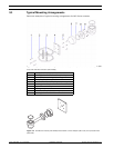
Number Description
1 Biphase connection between MIC power supply and head-end control system
2 Video connection between MIC power supply and head-end control system
3 Shielded composite cable between MIC camera and MIC power supply
4 Head-end control system (with Divar 400 or 600 or similar) with appropriate links