


MIC612 Thermal Camera Installation | en 19
Bosch Security Systems, Inc. Installation Manual F.01U.249.416 | 2.0 | 2012.09
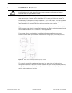
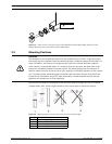
4.3 Mounting the Camera
To mount a MIC Series camera, follow these steps:
1. Identify a secure location for the mount and for the camera. Locate the mounting position
so that the camera cannot be interfered with intentionally or accidentally. Ensure that the
installation location has the appropriate clearance from power and lightning conductors,
in accordance with NEC725 and NEC800 (CEC Rule 16-224 and CEC Section 60). Do not
install the camera near:
– Any heat sources
– Any overhead power lines, power circuits, or electrical lights, or where it may
contact power lines, circuits, or lights
2. Ensure that the mounting surface is capable of supporting the combined weight of the
camera and mounting hardware under all expected conditions of load, vibration, and
temperature. MIC612 cameras must be secured to one of the following surfaces:
– Concrete Solid/Cast
– Concrete Masonry Unit (Concrete Block)
– Brick (all types)
– Metal (Steel/Aluminum, minimum 1/8-in. thick)
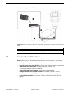
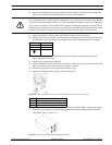
Note: If the camera is positioned in a highly exposed area where lightning strikes may occur, it
is recommended to install a lightning conductor within 0.5 m of the camera and at least 1.5 m
higher than the camera. The construction of the camera housing itself is capable of coping
with secondary strikes. If the correct lightning protection is applied, no damage to the internal
electronics or camera should result. An earth bonding connection to the case also provides
protection against damage from secondary strikes. (See step 8.)
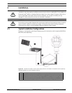
3. Fit the mounting brackets securely, observing all appropriate safety precautions and local
building regulations.
4. Carefully lift the camera to the mounting point.
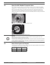
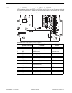
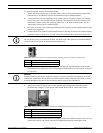
5. Connect the female 14-pin connector end of the shielded composite cable to the male
plug in the base of the camera. Screw the cable connector sleeve onto the plug until it is
firmly secured (approximately four (4) turns from the start of thread engagement).
6. Earth the camera using one of the supplied securing bolts. Only earth the camera at a
single point to prevent earth loops and video distortion (hum bars), caused by electrical
interference, from appearing on the camera picture in the control room. Please note:
– The camera module and housing are electrically isolated, so the housing should be
safety earthed regardless. The safety earth should be a bonding connection (for
CAUTION!
Fasteners are not supplied with MIC612 cameras because the type of fastener used depends
on the material to which the fastener is attached. The material must accommodate a minimum
pull-out strength of 275 kg (600 lbs.) Fasteners can include wedge anchors, sleeve anchors,
single expansion anchors, double expansion anchors, machine screw anchors, or "Thru-
Bolting" with a nut. All fasteners must be made of 303(A2) stainless steel, at a minimum, with
a diameter of 8 mm (5/16-in). All bolts must extend fully through the mounting surface and be
secured with a flat washer, lock washer, and a nut. All studs must be anchored to concrete or
welded to a steel backing plate. Anchor bolts can be used for blind structures where there is
no access to the rear.
NOTICE!
MIC 612 cameras have an internal fuse for protection. The fuse (XF4001) is a non-serviceable
part and must be replaced at a Bosch Service Center. DO NOT open the camera housing.