


MIC612 Thermal Camera Installation | en 27
Bosch Security Systems, Inc. Installation Manual F.01U.249.416 | 2.0 | 2012.09
* If connecting a heater, see Section 4.4.5 Commissioning the Camera with Heater Option Fitted.
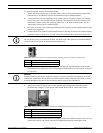
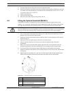
19. Slide back the cable so that the shield is in the middle of the gland.
20. Tighten the cable gland so that it grips firmly the shielded composite cable. It is
important that the braided cable screen engages with the internal clamps of the cable
gland to ensure correct EMC protection.
21. If necessary, connect a tamper switch to terminal block HD2.
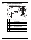
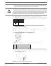
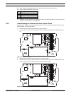
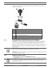
22. Make the necessary video connections. Feed the coaxial cable of your choice--see the
table below to identify the recommended cable types, maximum distance, and other
specifications for the coax video connection between the MIC power supply and the
head-end control system--through the top-left M12 cable gland (item 1, Figure 4.7).
23. Crimp the end of the cable with a BNC terminal connector.
24. Connect the Video Out cable to BNC socket CN1.
25. For dual video output only: If needed, remove the blanking plug that covers the hole for
the bottom-left M12 cable gland (item 3, Figure 4.7). Feed a second Video Out cable
through the cable gland, and then connect the switched Video Out cable to BNC socket
CN3. This second cable provides control for video from both the optical camera and the
thermal camera; users can switch between the two cameras.
26. Feed telemetry cable through the bottom-right M12 cable gland (item 4, Figure 4.7).
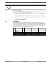
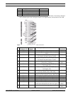
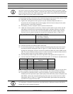
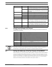
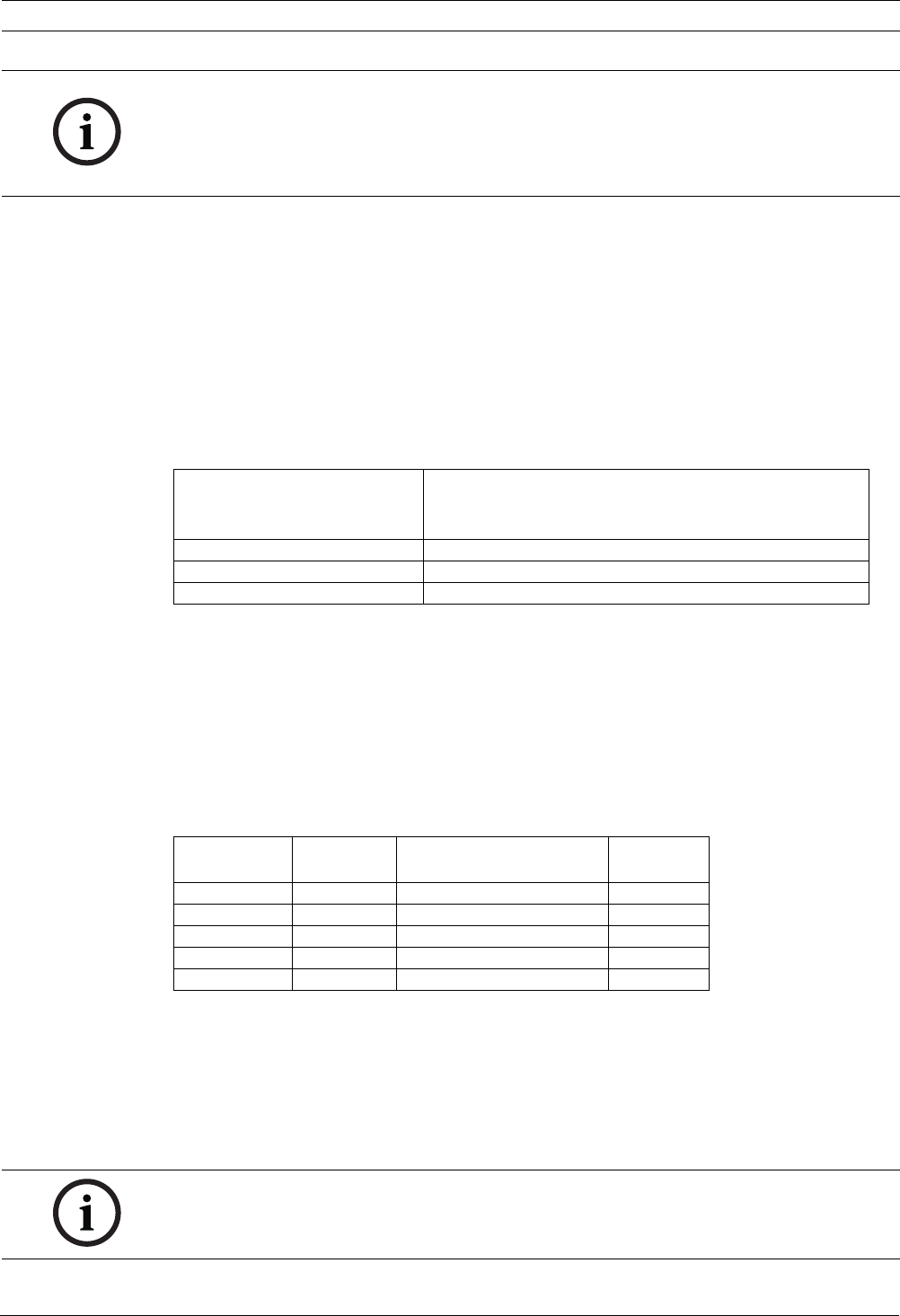
27. Connect head-end RS-485 control to terminal block HD5, as indicated in the table below:
Note: The terminal block is positioned with the screw terminals on the left, next to the fuses.
Pins are numbered from top to bottom in that orientation. Non-IR PSU PCBs are marked.
28. If connecting to additional add-on cards (for example, a card for 8-input alarms (MIC-
516ALM) or for 8-input alarms plus washer pump drive (MIC-ALM), and/or a Biphase card
(MIC-BP4)), remove the second blanking plug that covers one of the holes for an M12
cable gland (item 3, Figure 4.7). Attach the supplied M12 gland. Make the appropriate
connections to plug-in terminal CN2.
NOTICE!
You must connect the overall shield drain wire of the composite cable to the power supply
chassis in order to ground the chassis. Crimp the drain wire to the ring terminal lug attached
to the mounting screw of the PCB located to the right of BNC socket CN3 (Video Switched).
Refer to Figure 4.3 for the location of the screw.
Cable Type; Maximum Distance RG-59/U; 300 m (1000 ft)
RG-6/U; 450 m (1500 ft)
RG-11/U; 600 m (2000 ft)
Size O.D. between 4.6 mm (0.181 in.) and 7.9 mm (0.312 in.)
Shield Copper braid: 95%
Central Conductor Standard copper center
PCB Marking
(non-IR PCBs)
Telemetry
Signal Name
Connection Description /
Function
Pin Number
RxB Rx + RS485+ to camera 1
RxA Rx - RS485- to camera 2
0V Ground 0V from control room 3
TxA Tx - RS485- to control room 4
TxB Tx + RS485+ to control room 5
NOTICE!
For installation of the MIC 8-input Alarm Card (MIC-ALM) or Biphase converter (MIC-BP4),
please refer to their respective manuals.