


MIC612 Thermal Camera Installation | en 21
Bosch Security Systems, Inc. Installation Manual F.01U.249.416 | 2.0 | 2012.09
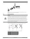
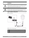
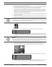
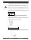
4.4.1 Earth Link on PCB
The printed circuit board (PCB) has one Earth Link option, near terminal block HD1, to allow
the PSU to be set up for different earthing schemes:
– If there is a separate connection between video screen and earth, the Earth Link should
be broken. This usually occurs on copper-connected systems where all of the copper
video coaxes are taken back to the control room to be connected to a central earth point.
– If fiber optics or other indirect connections are used to get data and video to and from
the control room, then the Earth Link should be left intact, as long as it is the only
camera-end earth reference point.
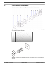
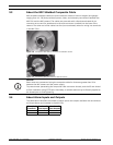
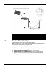
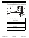
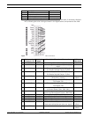
4.4.2 Fuse Ratings
The MIC PSUs for MIC612 cameras have four (4) off 20 mm fuses (numbers 13 - 16 in
Figure 4.3) in fuse holders. The ratings for these fuses are fixed on the low voltage secondary
side but change with input voltage on the high voltage primary side. The following table shows
the fuse values that should be fitted to provide proper protection for the MIC-240PSU-2 and
MIC-115PSU-2 power supplies. Note: FS 4 does not exist.
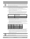
NOTICE!
Only use the specified power supplies with the MIC612.
Fuse
ID
Fuse Function Type Rating for 240 V
Primary
Rating for 115 V
Primary
Rating for 24 V
Primary
FS 1 MIC camera
protection
Glass 1.6 A anti-surge (T) 1.6 A anti-surge (T) 1.6 A anti-surge (T)
FS 2 Primary protection Glass 200 mA quick blow 500 mA quick blow 2.5 A quick blow
FS 3 Heater protection 1 Glass 1.6 A anti-surge (T) 1.6 A anti-surge (T) 1.6 A anti-surge (T)
FS 5 Heater protection 2 Glass 1.6 A anti-surge (T) 1.6 A anti-surge (T) 1.6 A anti-surge (T)