


22 en | Installation MIC612 Thermal Camera
F.01U.249.416 | 2.0 | 2012.09 Installation Manual Bosch Security Systems, Inc.
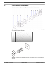
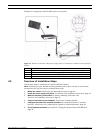
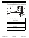
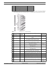
4.4.3 Layout of MIC Power Supply Units (PSUs) for MIC612
The figure below displays the layout of the PCB in the MIC PSUs for non-IR cameras, with call-
out numbers to the side of or below the connection/terminal ID or the terminal, and ’on’ the
fuses. The table below the figure identifies the connections.
Figure 4.3 Layout of MIC-240PSU-2 and MIC-115PSU-2
Number Connection /
Terminal ID on PCB
Description/Function ofConnection
/ Terminal
Type of Connection /
Terminal
1 HD1 AC Power input Screw terminal
2 HD3 Shielded composite cable
(connections to camera )
Screw terminal
3 HD5 RS-485 control Screw terminal
4 HD4 Telemetry header Molex connector
5 HD8 USB to RS-485 converter Molex connector
6 HD6 [Optional] Auxiliary, heater Screw terminal
7 HD7 Video (composite cable) Screw terminal
8 HD2 Tamper switch Screw terminal
9CN3(Video
Switched)
Coax connection
(Switched visible/thermal video out)
BNC socket
10 CN1(Video Out) Coax connection
(Visible video out)
BNC socket
11 CN2 Auxiliary card terminal Plug in
12 Earth Link Earth Link --
13 FS2 Fuse 2 - Primary protection --
14 FS1 Fuse 1 - MIC camera protection --
15 FS3 Fuse 3 - Heater protection 1 --
16 FS5 Fuse 5 - Heater protection 2 --