


47
F
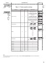
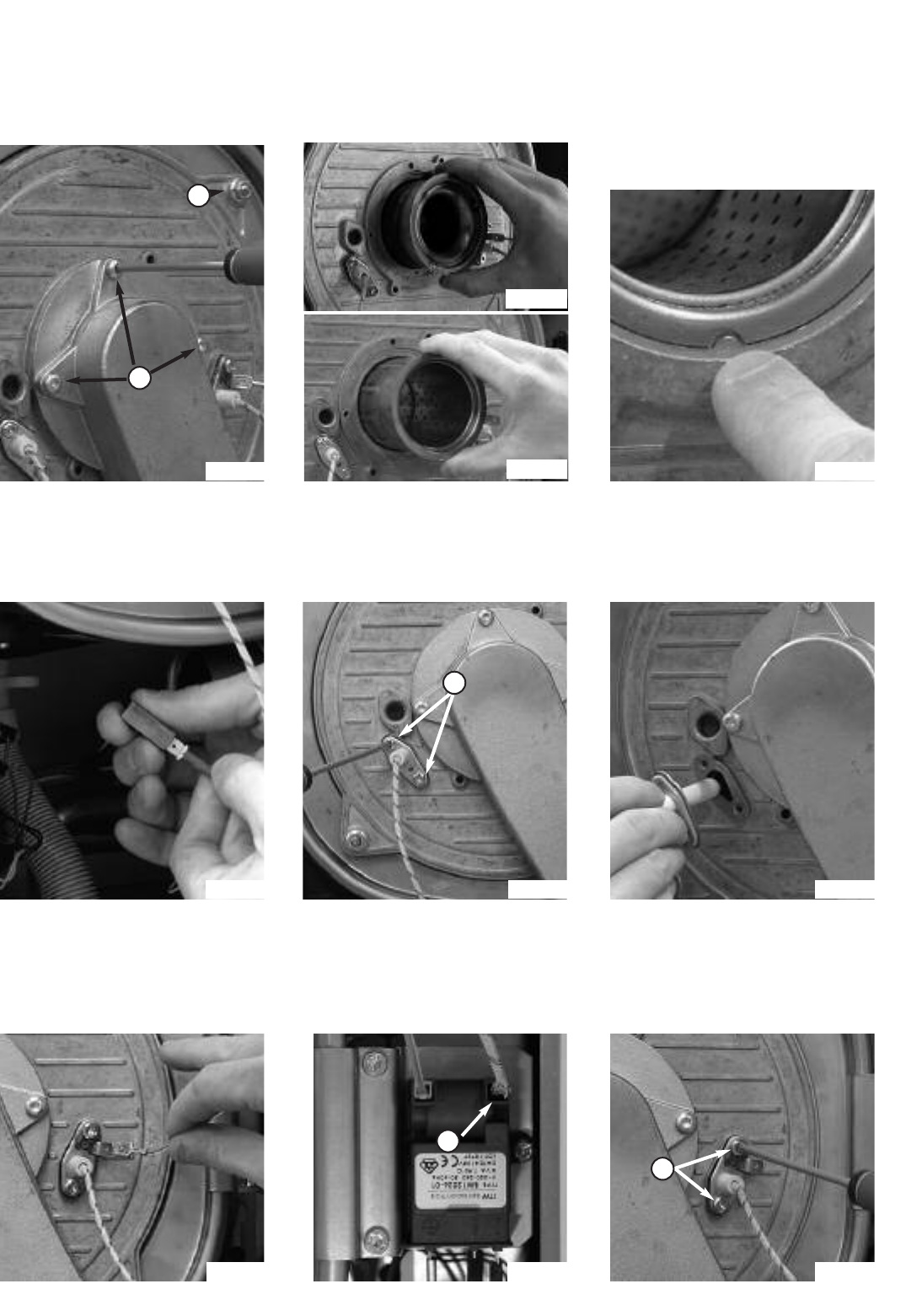
Fig. 58 Fig. 60
Fig. 61
Fig. 62 Fig. 63
Fig. 64 Fig. 65 Fig. 66
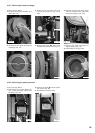
H
I
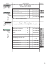
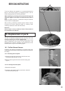
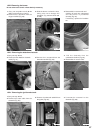
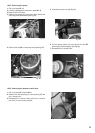
18.2.2 Removing the burner
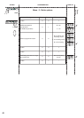
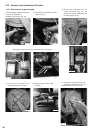
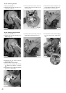
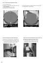
18.2.3 Removing the detection electrode
1
.
C
arry out step
1
8.1.1
a
nd
1
8.2.1
(without removing the 4 nuts D);
2. Remove the 3 screws F from the
air/gas manifold (Fig. 58)
;
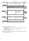
3. Slide the burner out from the front,
taking care not to damage the
insulation (Fig. 59a 24 kW & 59b
3
0 kW);
4. Reassemble in reverse order and
c
hecking all seals are undamaged
and the burner is positioned
c
orrectly (Fig. 60).
If necessary, replace the insulation
too.
1. Carry out step 18.1.1;
2. Disconnect the detection electrode
cable (Fig. 61);
3.Remove the 2 screws G from the
electrode manifold (Fig. 62);
4. Pull the electrode from the
combustion chamber (Fig. 63);
5. Reassemble in reverse order.
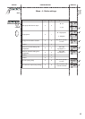
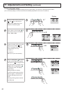
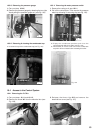
18.2.4 Removing the ignition electrode
1. Carry out step 18.1.1;
2. Remove the earth cable from the
electrode (Fig. 64);
3. Remove the electrode cable H from
the ignitor (Fig. 65);
4. Unscrew the 2 screws I on the
electrode (Fig. 66);
G
Fig. 59b
D
Fig. 59a
D
o not remove the burner unless absoluly necessary.