


12
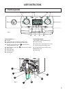
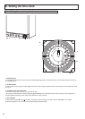
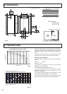
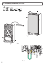
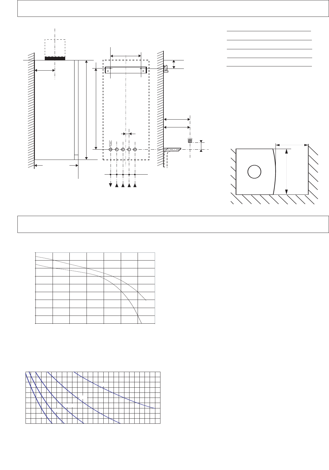
8. Dimensions
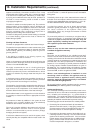
9. Hydraulic data
440
450 mini pour entretien
Fig. 8
54 54 54 54
JKLMN
I
JKLMN
32
296
141
289
2
1
720
691,5
121,5
I
172,5
4,7
All dimensions in mm
With packaging :
24 kW : 34 kg
30 kW : 37 kg
390
minimum space required 450
I S
afety valve C/H and condensate
J
H
eating flow
K Cylinder return (System Plus only)
L
Gas supply
M
Cold water supply
N
Heating return
296 (24 kW)
3
60 (30 kW)
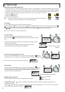
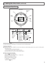
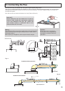
The boiler is fitted with an automatic by-pass as standard.
The graph (Fig. 9) shows the development of the pressure
available in relation to flow (on exit from the boiler ∆T
20°C).
To ensure correct operation, the minimum flow of the
appliance must be 300 l/h. (Thermostatic taps closed).
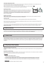
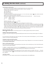
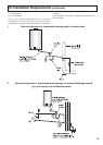
Capacity of the installation.
The water heater is fitted with a pressurised expansion
vessel.
Volumes : 6 litres
Pressure: 0,7 bar.
The volume of the expansion vessel in a pressurised
appliance varies according to:
- the average operating temperature in
°
C
- the static height, which is the difference in metres
between the highest point of the appliance and the
expansion vessel axis).
The minimum cold filling pressure of the appliance is 1 bar
(recommended pressure between 1.2 and 1.7 bar).
The pressure of the expansion vessel should always be
greater than the static height (in metres) divided by 10.
0
0.05
0.1
0.15
0
.2
0
.25
0
.3
0
.35
0.4
0
.45
0
200 400 600 800 1000 1200 1400
24 kW
30 kW
Pressure (bar)
flow rate (l/hr)
Pump Head Graph (15/50 & 15/60)
Fig. 9
20 40 60
80 100 120
Pf
140 160 180 200 220 240
1,0
1,1
1,2
1,3
1,4
1,5
1,6
1,7
1,8
1,9
2,0
Capacité maximale de l'installation (en litres)
260
Pression à froid pour le circuit chauffage (en bar)
280
40°C
50°C
60°C
70°C
80°C
C litre
Central heating initial pressure when cold (in bar)
System capacity chart
Fig. 10
1
62