


26
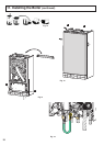
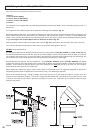
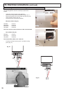
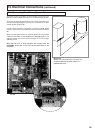
Making the Electrical Connections
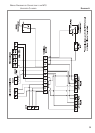
H
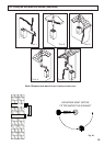
inge down the electrical box to gain access to the
electrical connections. Push in the tabs
P (Fig. 30)
o
n either side of the boiler and pivot the box for-
ward.
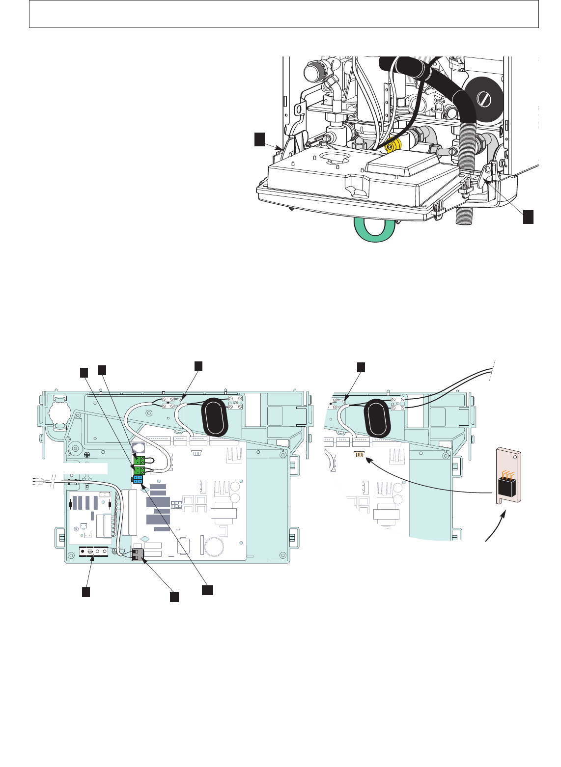
R
emove the PCB cover (see Section 18.4).
Connect the live neutral and earth wires to the main
c
able.
I
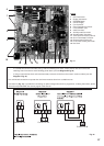
f using a room thermostat or other external control,
they can be connected in place of the link on the ter-
minal block (Diagram A- Fig. 32).
N
ote: Use only controls designed for voltage free
switching or 24V supply. Do not connect to a 230V
supply, and do not run 230v cables alongside the
low voltage cables.
All necessary settings for room thermostat opera-
tions are described in Section 17 ADJUSTMENTS
AND SETTINGS.
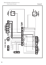
13. Electrical connections
P
P
Fig. 30
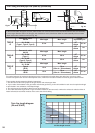
P1
P2
ON OFF
A1
A
2
A3
A4
B1
B2
B3
B4
P3
S
T
D
J12
J1
J12
J1
F
Cable 230 V 2P + T
P
1
P2
ON OFF
A1
A2
A
3
A4
B1
B2
B
3
B
4
P
3
S
T
D
J
12
J
1
J12
J1
F
Cylinder
thermistor
System A
System A Plus
System A Plus
change the EEPROM on PCB