


4
INTRODUCTION
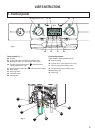
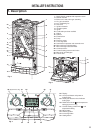
The System A is a fully automatic, wall mounted, low water content condensing system boiler. It is a room sealed,
fan assisted, balanced flued appliance providing central heating. It has electronic ignition and is suitable for all
modern electrical control systems. The boiler is designed for sealed systems only and a circulating pump,
expansion vessel together with a pressure gauge and safety valve are included within the boiler.
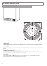
The standard horizontal flue kit is suitable for lengths 300 mm minimum to 600 mm maximum and includes an
elbow adapter that can be rotated through 360 ° . The horizontal flue can extend up to 3 metres using 1 metre
flue extension kits. 45 ° and 90° flue bends are also available as accessories.
The System
A Plus
includes a diverter valve and so can provide central heating and hot water flow for an indirect
cylinder.
SERVICING INSTRUCTIONS
18 REPLACEMENT OF PARTS .........................................................................................................................45
18.1 To Gain General Access........................................................................................................................45
18.1.1 Removing the front panel.......................................................................................................................45
18.1.2 Lowering the control panel.....................................................................................................................45
18.2 Access to the Combustion Chamber .....................................................................................................46
1
8.2.1
R
emoving the combustion chamber front panel ....................................................................................46
18.2.2 Removing the burner .............................................................................................................................47
1
8.2.3
R
emoving the detection electrode .........................................................................................................47
18.2.4 Removing the ignition electrode.............................................................................................................47
1
8.2.5
R
emoving the fan...................................................................................................................................48
18.2.6 Removing the gas valve.........................................................................................................................48
18.2.7 Removing the heat exchanger...............................................................................................................49
18.2.8 Removing the spark generator...............................................................................................................49
18.3 ACCESS TO THE WATER CIRCUIT ....................................................................................................50
18.3.1 Drain down.............................................................................................................................................50
18.3.2 Removing the 3 way valve.....................................................................................................................50
18.3.3 Removing the 3 way valve shutter.........................................................................................................50
18.3.5 Removing the pump...............................................................................................................................51
18.3.6 Removing the pressure relief valve ......................................................................................................51
18.3.7 Removing the domestic expansion vessel.............................................................................................52
18.3.8 Removing the overheat thermostat........................................................................................................52
18.3.9 Removing the temperature sensors (NTC’s) .........................................................................................52
18.3.10 Removing the pressure gauge...............................................................................................................53
18.3.11 Removing the DHW flow switch.............................................................................................................53
18.3.12 Removing & cleaning the condensate trap............................................................................................53
18.4 ACCESS TO THE CONTROL SYSTEM ...............................................................................................53
18.4.1 Removing the PCB’s..............................................................................................................................53
18.4.2 Removing the fuses...............................................................................................................................54
18.5 CONNECTING THE EXTERNAL SENSOR ..........................................................................................54
19 INCORRECT FUNCTION......................................................................................................................55
20 GAS CONVERSION .............................................................................................................................56
21 INCORRECT FUNCTION......................................................................................................................
56
22 MAINTENANCE INSTRUCTIONS.........................................................................................................57
22.1 GENERAL REMARKS...........................................................................................................................57
22.2 CLEANING THE PRIMARY EXCHANGER...........................................................................................57
22.3 OPERATIONAL TEST...........................................................................................................................57
23 SHORT SPARES LIST
..........................................................................................................................58
24 TECHNICAL DATA................................................................................................................................59
25 BENCHMARK COMMISSIONING CHECKLIST
....................................................................................61
26 SERVICE INTERVAL RECORD............................................................................................................62