


17
Please check that you are familiar with the installation requirements before commencing work (Section 10).
The installation accessories described in the following list are included in the boiler packaging:
- Hanging bracket
- A paper template (showing the dimensions of the boiler with 5 mm side clearances)
- Connection tails and valves
- Screws and washers
- Connection washers
- Installation, Servicing and Operating Instructions
-
Air Inlet Header (for use with twin flue pipe)
- Guarantee Card
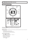
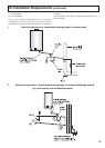
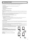
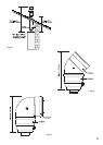
Method of positioning the boiler on the wall.
The paper template can be used to ensure the correct positioning of kitchen cabinets etc. It also details the commissioning
instructions.
The paper template has to be fixed to the wall and used to locate the position of the hanging bracket and the centre for the flue
hole.
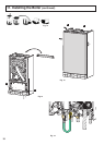
Drill and plug the wall and secure the hanging bracket using the screws provided. Remove the boiler from its packaging as
shown in Fig. 12, unscrew the clamp locking bolt
A and remove the casing (Fig. 13).
Place the boiler on the wall on the hanging bracket (Fig. 14).
NO
TE
: TH
E APPLIANCE MUST NOT BE FITTED ON A COMBUSTIBLE WALL SURFACE
.
Connecting the boiler to the system
- Remove the boiler casing as described in Section 18.
- Push in the tabs “
P” (Fig. 14) on either side of the boiler and pivot the electrical box forward to gain access to the valve
connections
- Remove the caps and connect the valves to the boiler using the washers provided in the plastic bag.
2 x fibre washers for the C/H flow and return.
1 x rubber washer for gas connection
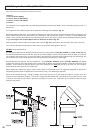
Safety valve discharge
The pressure relief valve tube is made of copper. It should terminate below the boiler safely outside the premises. Care should
be taken that it does not terminate over an entrance or window or where a discharge of heated water could endanger
occupants or passers by.
Fill the Central Heating and DHW system and bleed air from the system as described in Section 14 .
The system should be carefully checked for leaks, as frequent refilling could cause premature system corrosion or
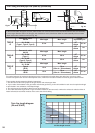
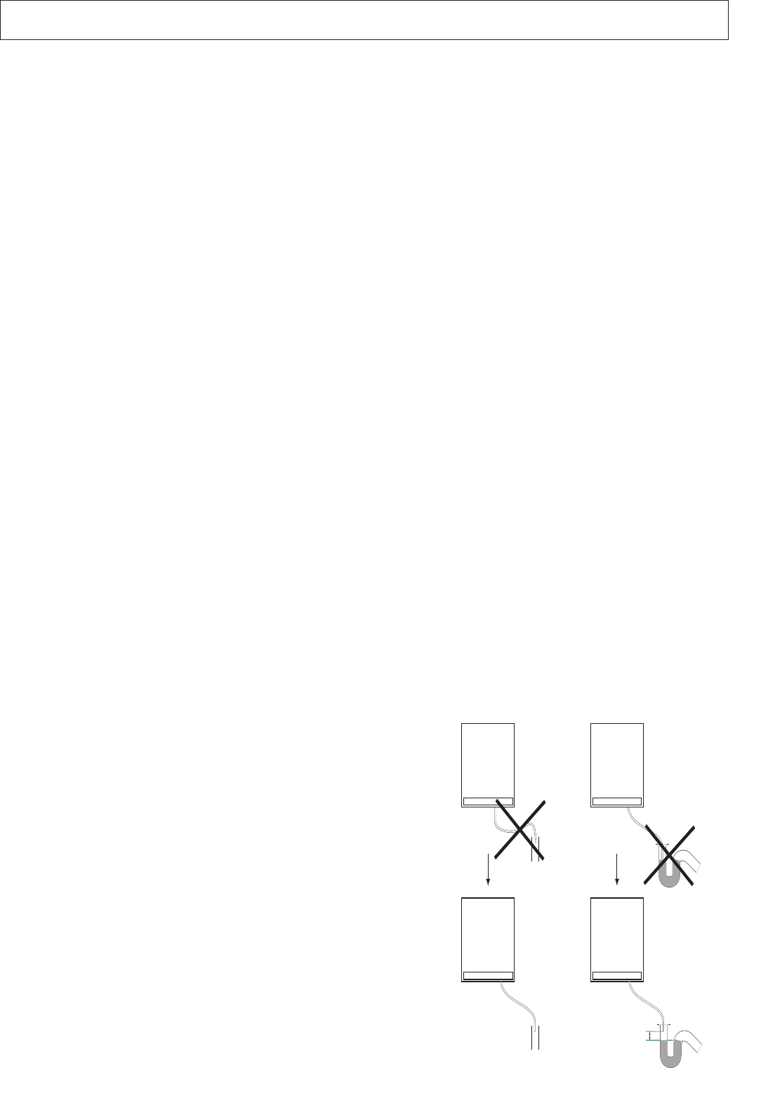
unnecessary scaling of the heat exchanger. The condensate pipe from the siphon (11 Fig. 6) should be connected to a drain
as described in the relevant Brittish regulations.
Pay special attention to not bend the plastic condensate drain pipe in such a way as to cause the flow to be interrupted. Please
use exclusively drain pipe material compatible with condensate products. (refer to
BS 6798 : 2000)
The condensate flow can reach 2 litres / hour; because of the acidity
of the condensate products (Ph close to 2), take care before
operation.
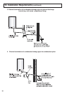
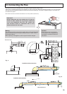
Fitting the Horizontal Flue
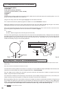
Attention ! Before starting the boiler, the trap (11 Fig. 6) must be
filled with water. Before fitting the flue onto the boiler, pour 1/4
litre of water into the exhaust pipe as shown in Fig. 15 (page 19).
Instructions on fitting the flue can be found in Section 12.
IMPORTANT!!
Use only the specific condensation flue kit supplied by MTS
(GB) Limited.
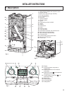
11. Installing the Boiler