


22
NO
TE
:
S
E
E PAGE
2
4
F
OR MAXIMUM AND MINIMUM FLUE RUNS
.
CONTENTS:
1X SI
LICONE
O-RI
NG
(60mm)
1X CO
NICAL
AD
APTOR
(60/100mm)
1
X VE
RTICAL
FL
UE
KI
T
(80/125mm)
3X SC
REWS
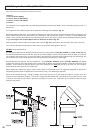
The vertical flue kit is supplied with a specially designed weather proof terminal fitted, it can be used either with a flat roof or a
p
itched roof.
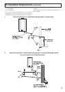
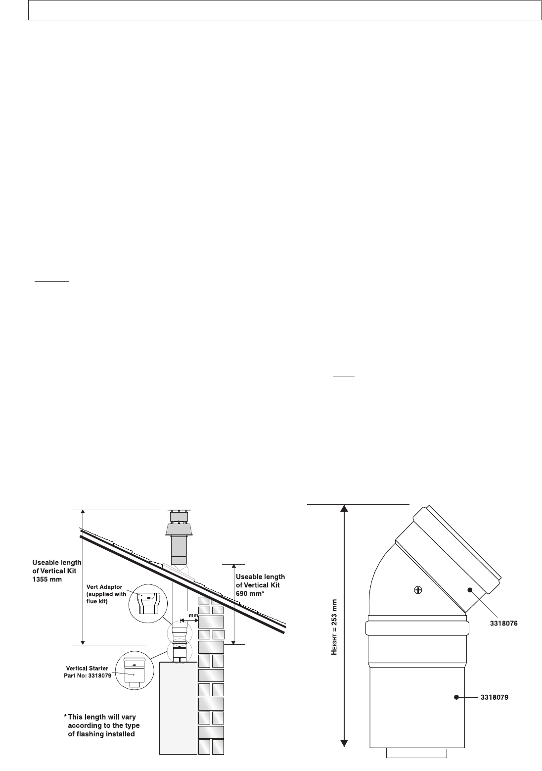
T
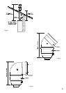
he Vertical flue kits useable lengths with the pitched roof flashings are indicated in
F
ig. 23
.
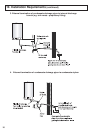
B
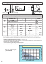
efore proceeding to fit the flue, ensure that the maximum flue length has not been exceeded (See the tables on Page 24) and
that all elbows and bends have been taken into consideration, the maximum flue length is 4 metres, for each additional 90
o
elbow 1 metre must be subtracted from the total flue length, and for each 45
o
0.5 metres must be subtracted from the total flue
length
(the height of the vertical adaptor and a 45
o
bend can be seen in Fig. 24).
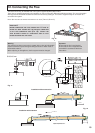
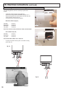
Mark the position of the flue hole in the ceiling and/or roof (see Fig. 23 for the distance from the wall to the centre of the flue).
Cut a 120 mm diameter hole through the ceiling and/or roof and fit the flashing plate to the roof.
DO NOT cut the vertical flue kit.
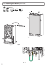
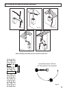
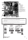
To connect the vertical flue kit directly to the boiler, place the vertical starter kit
(Part No. 3318079) (see Figs. 23 and 24) onto
the exhaust manifold and secure with the clamp, fit the vertical adaptor onto the vertical starter kit (note: there is no need to
use a clamp to secure this as it is a push fit connection), the vertical flue kit must then be inserted through the roof flashing, this
will ensure that the correct clearance above the roof is provided as the terminal is a fixed height.
Should extensions be required, they are available in 1 metre
(Part No. 3318077), 500mm (Part No. 3318078) and 160mm
lengths, they must be connected directly to the vertical starter kit before connecting the adaptor to allow the vertical flue kit to
be fitted. In the event that extension pieces need to be shortened, they must only be cut at the male end and it must be
ensured that the inner and outer flue remain flush.
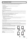
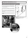
When utilising the vertical flue system, action must be taken to ensure that the flue is supported adequately to prevent the
weight being transferred to the appliance flue connection by using 1 flue bracket per extension.
When the flue passes through a ceiling or wooden floor, there must be an air gap of 25 mm between any part of the flue
system and any combustible material. The use of a ceiling plate will facilitate this. Also when the flue passes from one room
to another a fire stop must be fitted to prevent the passage of smoke or fire, irrespective of the structural material through
which the flue passes.
12.3 Fitting the Coaxial Flue (Ø 60 / 100 Vertical)
Fig. 23
Fig. 24
162