


29
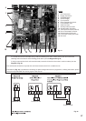
FIG. 38
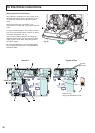
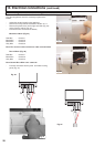
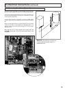
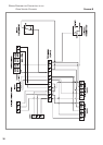
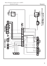
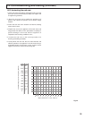
13. Electrical Connections (continued)
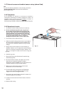
13.2 Connecting Zone Valves (System A)
The boiler can be connected to a central heating system that uses
two zone valves to allow connection to an indirect storage cylinder.
There are two wiring diagrams shown, one for the connection to an
U
nvented Cylinder (Diagram. A) and one for connection to an open
vented cylinder (Diagram B).
In both cases the boiler connection is shown as
R
OOM
, which
r
elates to the terminal on the PCB for external controls (see
1
2F
IG.
31
).
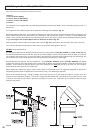
When connecting the boiler to an external cylinder do not run 240V
cables and the cables for the R
OOM
terminal (Fig. 38) together, use
separate cables to prevent induced voltage on the low voltage
s
witching circuit.
NOTE:THEUSEOFA‘Y’ PLAN SYSTEM IS NOT POSSIBLE WITH THE
SYSTEM A BOILER DUE TO THE LOW VOLTAGE SWITCHING OF THE
APPLIANCE
.
* IM
PORTANT
!!
EN
SURE THAT A BALANCING VALVE IS FITTED ON THE
CYLINDER R
ETURN
AND BALANCED CORRECTLY AT
C
OMMISSIONING STAGE
.
*