


24
123,5
200
107
25
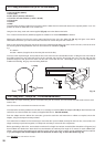
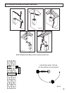
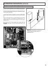
Fig. 27
ø 100
6
0 mm
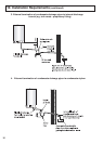
In the event that twin flue pipes are used, and the boiler has a side clearance of less than 60mm from the wall, it is necessary
t
o cut a larger diameter hole for the flue pipe, this should be ø10 cm, this will then allow for easier assembly of the air intake
elbow and the tube outside the wall (see Fig. 28).
F
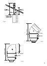
ig. 28
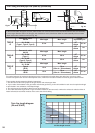
0 10 20 30 40 50 60
0
10
20
30
40
50
60
70
0
20
40
60
80
100
120
140
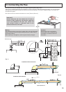
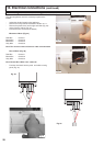
Air inlet length in meter
Horizontal flue exhaust length in meter
Minima HE 24, 30 & 35 FF
Vertical flue exhaust length in meter
Working area
Twin flue length diagram
(24 and 30 kW)
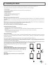
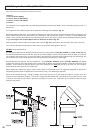
12.4 Fitting the twin pipe flue (Ø80/80) (continued)
For coaxial systems, the maximum development value, mentioned in the table above also takes into account an elbow.
For twin flue systems the maximum development value, mentioned in the table includes the exhaust gas/air intake terminal.
Type 5 outlets should respect the following instructions:
1- Use the same ø 80 mm flue pipes for the gas intakes and exhaust gas ducts.
2- If you need to insert elbows in the gas intake and exhaust gas ducts, you should consider for each one the equivalent length
to be included in the calculation of developed length.
3- The exhaust gas duct should jut above the roof by at least 0.5 m.
4- The intake and exhaust gas ducts in Type 5 must be installed on the same wall, or where the exhaust is vertical and the air
intake horizontal, the terminals must be on the same side of the building.
TABLE
A
Concentric outlet
60/100
Min length Max. length
Length
equivalency for
24 , 30 kW
(Type 1, Type 2, Type 3)
0.3 m 10m
45
o
elbow
0.5 m
90
o
elbow
1 m
TABLE
B
Concentric outlet
80/125
Min length Max. length
24 , 30 kW
(Type 1)
0.3 m 30 m
45
o
elbow
0.5 m
24 , 30 kW
(Type 2, Type 3)
0.3 m 35 m
90
o
elbow
1 m
TABLE
C
Twin flue outlet
24 , 30 kW
Min length Max. length
Type 4
80/80
10 m
70 m
(35m air / 35m exhaust)
45
o
elbow
1.4 m
Type 5
80/80
10 m
70 m
(35m air / 35m exhaust)
90
o
elbow
2.2 m