


20
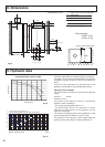
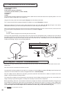
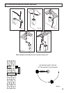
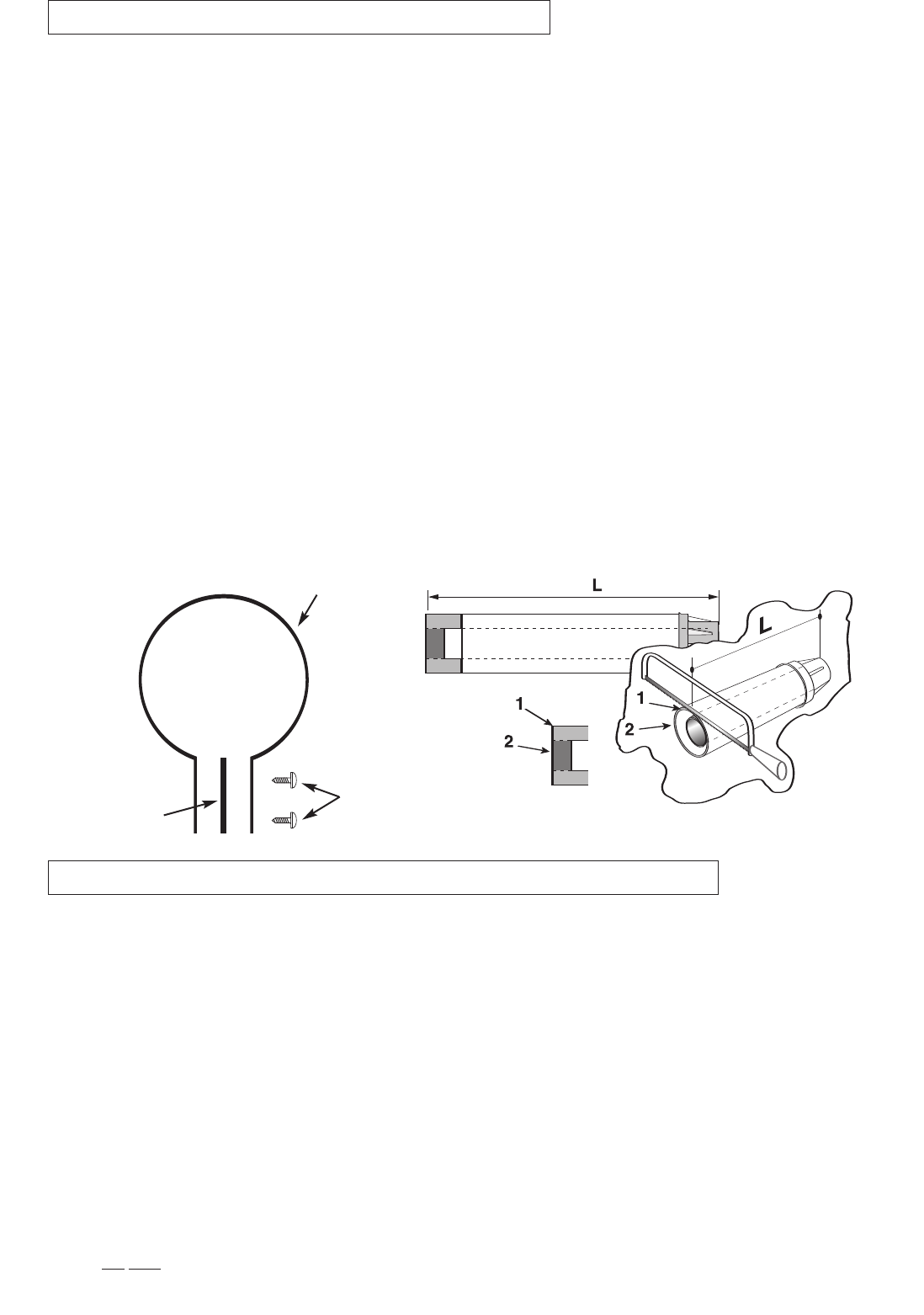
Fig. 19
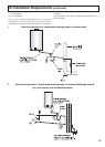
12.2 Fitting the 5” Flue (Ø 80 / 125 Horizontal/vertical)
Screws
Clamp
Seal
CO
NTENTS
:
1X SI
LICONE
O-RI
NG
(60mm)
1X EL
BOW
(90
O
)
2X WALL SEALS (
I
NTERNAL &
E
XTERNAL)
1
X FLUE PIPE INCLUDING TERMINAL (1 METRE - 60/100)
1X FLUE CLAMP
1X SC
REWS
1x Seal
Once the boiler has been positioned on the wall, insert the elbow into the socket and rotate to the required position. N
OTE
: It is
possible to rotate the elbow 360
o
on its vertical axis.
Using the flue clamp, seals and screws supplied
(Fig 19) secure the elbow to the boiler.
The 1 metre horizontal flue kit (3318073) supplied is suitable for an exact
X dimension of 815mm.
M
easure the distance from the face of the external wall to the face of the flue elbow
(
X - Fig 17),
t
his figure must now be
subtracted from 815mm, you now have the total amount to be cut from the plain end of the flue.
Draw a circle around the outer flue and cut the flue to the required length taking care not to cut the inner flue, next cut the inner
flue ensuring that the length between the inner and outer flue is maintained.
(Fig 19).
e.g.
X = 555mm
815-555 = 260mm (Length to be cut from the plain end of the flue).
Once cut to the required length, ensure that the flue is free from burrs and reassemble the flue. If fitting the flue from inside of
the building attach the grey outer wall seal to the flue terminal and push the flue through the hole, once the wall seal has
passed through the hole, pull the flue back until the seal is flush with the wall. Alternatively, the flue can be installed from
outside of the building, the grey outer seal being fitted last.
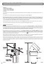
12.1 Fitting the coaxial flue (Ø 60/100 Horizontal)
Should the flue require extending, the flue connections are push fit, however, one flue bracket should be used to secure each
metre of flue.
N
OTE:
S
EE
PAGE
24 FOR
MAXIMUM
AND MINIMUM FLUE RUNS
.
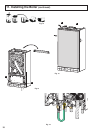
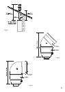
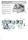
Once the boiler has been positioned on the wall, it is necessary to insert the
Ø 80/125 adaptor (FIG. 20) for both horizontal and
vertical flue runs into the boiler flue socket (not supplied with flue kit -
Part No 3318095).
Push the adaptor onto the boilers flue connection, grease the seals then add extensions or elbows as required, secure the
adaptor, using the clamp and screws provided.
To fit extensions or elbows it is first necessary to ensure that the lip seal is fitted correctly into the inner flue, once verified, it is
simply necessary to push them together, no clamps are necessary to secure the flue components.
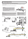
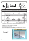
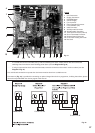
Before proceeding to fit the flue, ensure that the maximum flue length has not been exceeded (See the tables on Page 23) and
that all elbows and bends have been taken into consideration, the maximum flue length is 10 metres, for each additional 90
o
elbow 1 metre must be subtracted from the total flue length, and for each 45
o
0.5 metres must be subtracted from the total flue
length (the height of the vertical adaptor and a 45
o
bend can be seen in Fig. 21 and a 90
o
bend in Fig. 22).
N
OTE: DO NOT CUT THE VERTICAL FLUE KIT.