


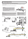

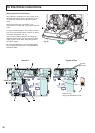
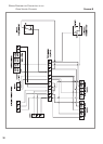
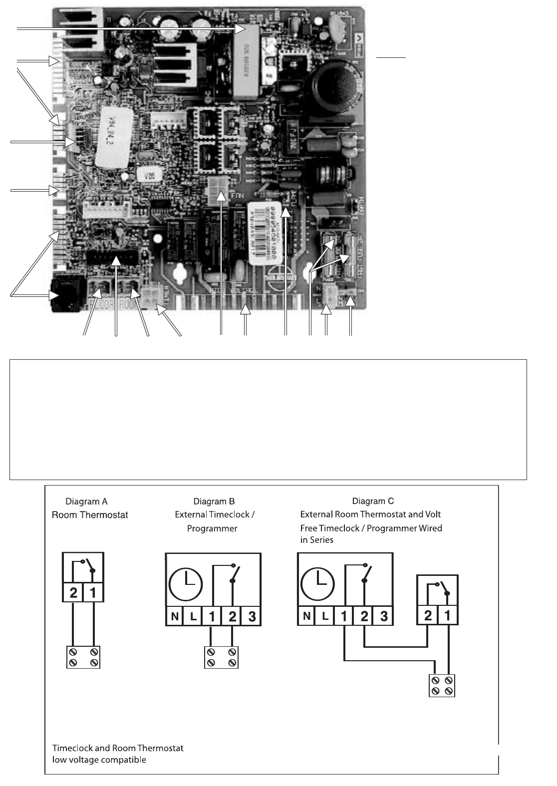
27
Fig. 31
LEGEND
1 NTC Connectors
2 D
isplay Connectors
3 EEPROM Button
4 24V DC Supply
5 Fan Connector
6 F
lame Detection Connector
7 Fuses 2A 230V (X2)
8 230V Connector
9 Auxillary 230V Connector
10 Actuators 230V Connector
11 Time Clock Connector (Internal)
12 Room Thermostat Connector
13 Remote Control Connector
14 Under Floor Heating Connector
15 Not Used
1
5
1112
13
14
15
2
3
4
8
97
6
10
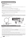
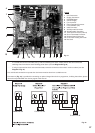
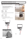
- If a remote time clock is to be fitted, using a volt-free switching time clock, remove the link wire and connect the
switching wires from the time clock following points above (see also
Diagram B Fig. 32).
- If using an external time clock and room thermostat, remove the link wire and connect in series as above (see also
Diagram C Fig. 32).
Live and Neutral connections to operate the clock motor must be taken from a suitable source.
Connector
11 (Fig. 31), is provided for connecting an optional integral time clock or programmer, for fitting instructions, please
refer to those provided with the clock or page 8 of this manual.
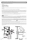
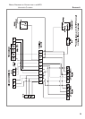
Fig. 32
CONNECTOR 12
CONNECTOR 12
CONNECTOR 12