


Camera interfaces
Hardware Installation Guide V2.0.0
52
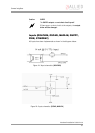
Triggers
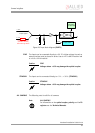
ALL CAMERAS The following note is valid for all cameras:
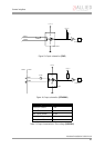
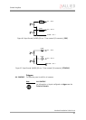
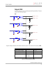
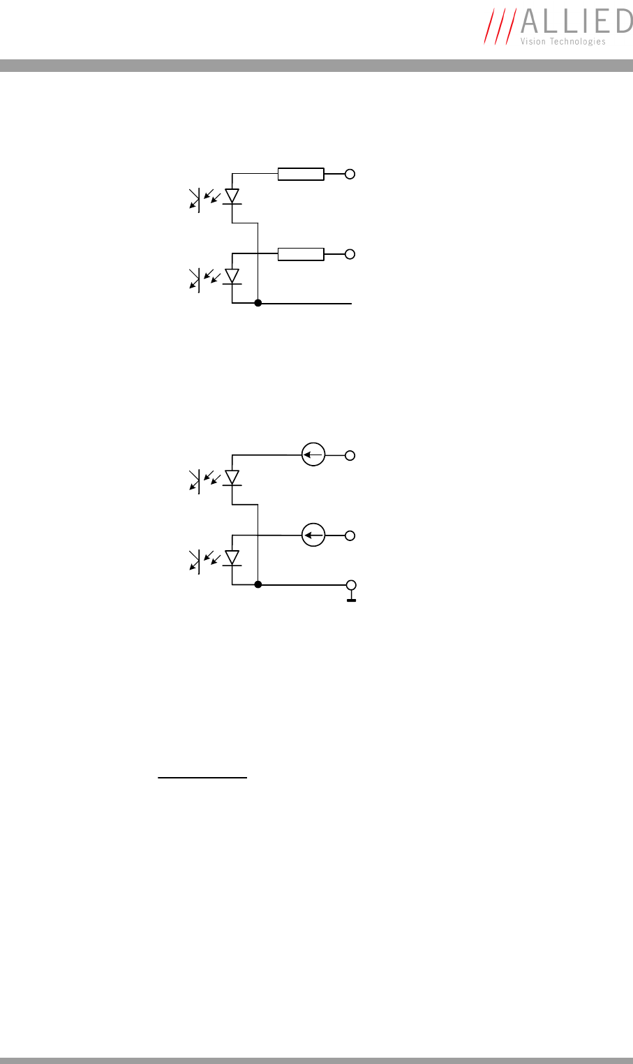
Figure 26: Input Ground (InGND) (Pin no. 7 from camera I/O connector) (PIKE)
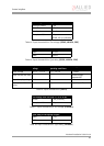
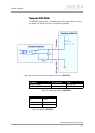
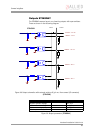
Figure 27: Input Ground (InGND) (Pin no. 7 from camera I/O connector) (STINGRAY)
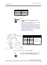
Note
L
ALL CAMERAS
For information on inputs configured as triggers see the
Technical Manuals.
In1 – Pin 4
390R
390R
In2 – Pin 11
InGND – Pin 7
In1 – Pin 4
In2 – Pin 11
InGND – Pin 7
8 mA
8 mA