


Camera interfaces
Hardware Installation Guide V2.0.0
45
PIKE and STINGRAY family
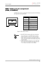
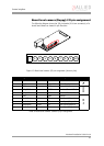
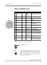
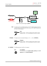
Figure 20: Camera I/O connector pin assignment
Note
L
GP = General Purpose
Note
L
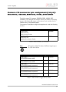
Pin 1 is not internally bridged with pin 7 to avoid ground
noise being induced in the camera and to prevent ground
loops. Use pin 1 only if you want to power the camera by
HIROSE or to connect to the serial interface of the camera in
combination with pin 8 and 9.
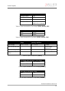
Pin Signal Direction Level Description
1External GND GND for
RS232 and
ext. power
External Ground for RS232
and external power
2 ExtPower +8...+36 V DC Power Supply
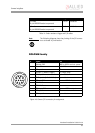
3 CameraOut4 Out Open emitter Camera Output 4 (GPOut4)
default: -
4 CameraIn1 In CMOS / TTL
8-36 V
Camera Input 1 (GPIn1)
default: Trigger
5 CameraOut3 Out Open emitter Camera Output 3 (GPOut3)
default: Busy
6 CameraOut1 Out Open emitter Camera Output 1 (GPOut1)
default: IntEna
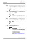
7 CameraIn GND In Common GND
for inputs
Camera Common Input
Ground (In GND)
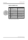
8 RxD_RS232 In RS232 Terminal Receive Data
9 TxD_RS232 Out RS232 Terminal Transmit Data
10 CameraOutPower In Common VCC
for outputs
max. 35 V DC
Camera Output Power
for digital outputs (OutVCC)
11 CameraIn2 In CMOS/TTL
8-36 V
Camera Input 2 (GPIn2)
default: -
12 CameraOut2 Out Open emitter Camera Output 2 (GPOut2)
default: Follow CameraIn2