


Camera interfaces
Hardware Installation Guide V2.0.0
43
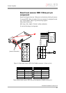
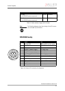
DOLPHIN family
I/O cable
12-pin HIROSE female to open end
5.0 m K1200193
I/O cable
12-pin HIROSE female to open end
10.0 m K1200194
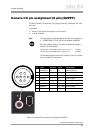
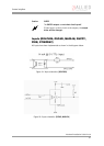
Note
L
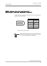
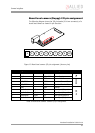
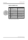
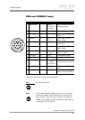
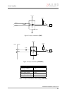
The following diagrams show the pinning of the I/O connec-
tors as viewed in pin direction.
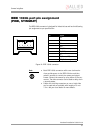
Figure 18: Camera I/O connector pin assignment
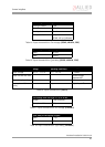
Order text Length Order number
Table 11: Order numbers: trigger and I/O cables
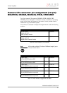
Pin Signal Use
1 External GND GND for RS232 and ext. power
2 Power IN 8-36 V DC
3 GPInput 3 TTL
4 GPInput 1 (default trigger) TTL, Edge, progr.
5 GPOutput3 Open collector
6 GP Output 1 (default IntEna) Open collector
7 GPInput GND Common GND for inputs
8RS232 RxD
9RS232 TxD
10 GPOutput GND Common VCC for outputs
11 GPInput 2 TTL
12 GPOutput 2 Open collector