


Camera interfaces
Hardware Installation Guide V2.0.0
46
Operating the camera (DOLPHIN, OSCAR,
MARLIN, GUPPY, PIKE, STINGRAY)
DOLPHIN, OSCAR,
MARLIN, PIKE,
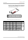
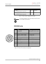
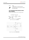
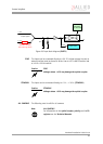
STINGRAY Power for the camera is supplied either via the FireWire™ bus or the camera
I/O connector's pin 2 (MARLIN: CCD models only).
GUPPY Power for the camera is supplied either via the FireWire™ bus or the camera
I/O connector’s pin 7.
ALL CAMERAS The input voltage must be within the following range:
Vcc min.: +8 V
Vcc max.: +36 V
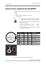
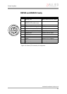
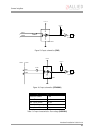
Control and video data signals
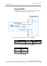
DOLPHIN cameras have 3 inputs and 3 outputs
OSCAR cameras have 2 inputs and 2 outputs.
MARLIN cameras have 2 inputs and 2 outputs.
GUPPY cameras have 1 input and 3 outputs. GUPPY board level cameras have
4 bidirectional inputs/outputs.
PIKE cameras have 2 inputs and 4 outputs.
STINGRAY cameras have 2 inputs and 4 outputs.
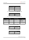
Note
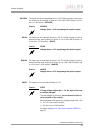
L
ALL CAMERAS
• An input voltage of 12 V is recommended for most effi-
cient use of the camera.
• As mentioned above (MARLIN: CCD models only): The
camera I/O supplies power to the camera via a diode.
This means that there is no power out at pin 2 (GUPPY:
pin 7) if the camera is powered via the bus. Consult the
factory if you need power output at this pin instead of
power in.
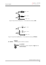
Note
L
ALL CAMERAS
Inputs and outputs can be configured by software. (GUPPY
board level: only outputs can be disabled via registers). For
a description of the different modes and the registers see the
Technical Manuals.