


43
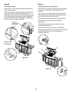
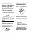
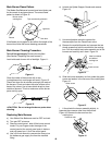
ij) To reinstall burners, reverse steps c) through i).
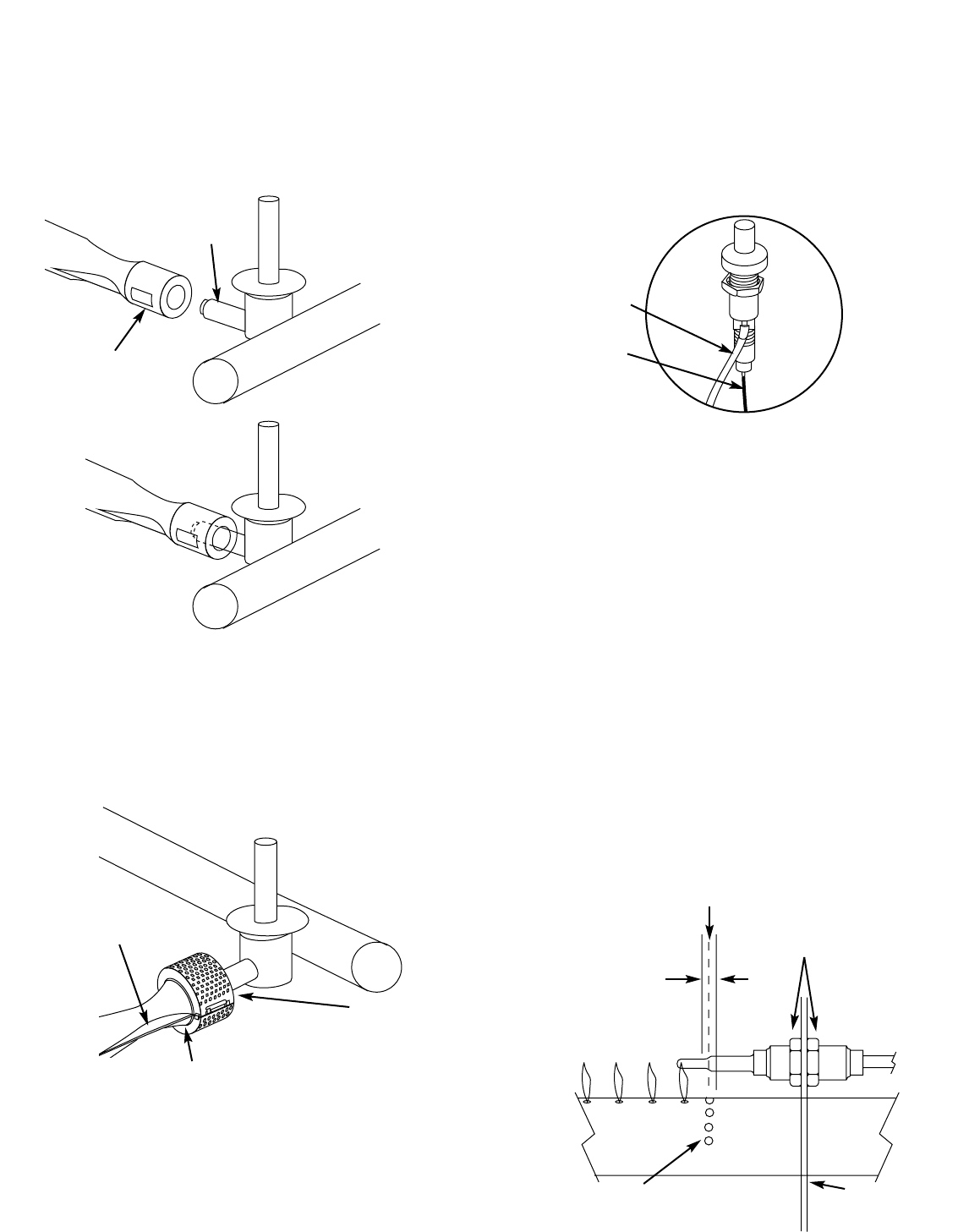
Venturi fin
Check fit around burner
Figure 18
Check fit around
valve
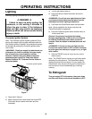
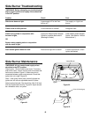
Crossover Ignition System Operations
If the Crossover Ignition System fails to ignite the Front
burner, light the Front burner with a match. If the Front
burner lights with a match, then check the Crossover
Ignition System.
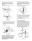
■ Check that both the white and black ignition wires
are attached properly. Figure 19.
■ Check that the Crossover Ignition button pushes the
igniter (button) down, and returns to the up position.
■ Check to see if the igniter is loose in the frame.
Tighten if necessary; see Step “Install igniter” for
correct procedure.
If the Crossover Ignition System still fails to light, contact
Weber-Stephen Customer Service.
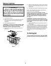
FlameCheck Safety System
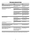
The correct positioning of the thermocouple probe is
shown in Figure 20. The tip of the probe is positioned in
the flame. The probe senses the heat from the Front
burner, and activates the FlameCheck valve. The valve
allows the gas to flow into the Front burner. If the Front
burner should go out for any reason, the thermocouple
probe will cool off, thereby closing the FlameCheck
valve, which stops the gas flow to the burners.
If the FlameCheck Safety System should fail to operate,
contact Weber-Stephen Customer Service.
Center line
Thermocouple nuts
Figure 20
1/8 inch
Ignition holes
Wall of
cooking box
Figure 19
White wire
Black wire
ƽCAUTION: If the Spider Stopper Guards do not fit
tightly, contact Weber-Stephen Customer Service.
ƽCAUTION: After reinstalling the gas lines, they
should be leak checked with a soap and water
solution before using the barbecue. (See Step
"Check for gas leaks".)
k) Reinstall the Spider Stopper Guards. Slightly rotate
the Spider Stopper Guards so that the seams are in
line with the Venturi fins. There should be no gaps
in the seams or in the fit around the burners and
valves. Figure 18.
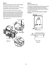
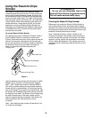
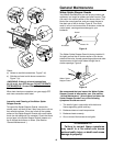
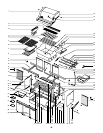
ƽCAUTION: The burner openings must be
positioned properly over the valve orifices.
Figure 17a.
Check proper assembly before fastening manifold in
place. Figure 17b.
Figure 17
Valve
Burner
(a)
(b)