


42
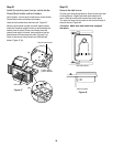
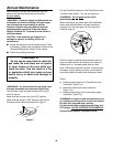
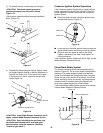
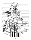
e) Unlatch the Spider Stopper Guards and remove.
Figure 13.
f) Use an adjustable wrench to remove the
thermocouple from the FlameCheck valve.
g) Remove the manifold bracket and unscrew the two
thumb screws that hold the manifold to the cooking
box. Pull the manifold and valve assembly out of the
burners and carefully set it down. Figure 14.
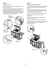
h) Slide the burner assembly out from under the guide
screw and washer in the corners of the cooking box.
Figure 15.
Figure 13
View from below
and behind
cooking box
Thumb screws
Figure 14
Guide screw
Figure 15
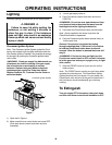
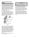
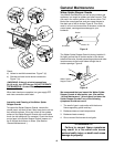
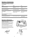
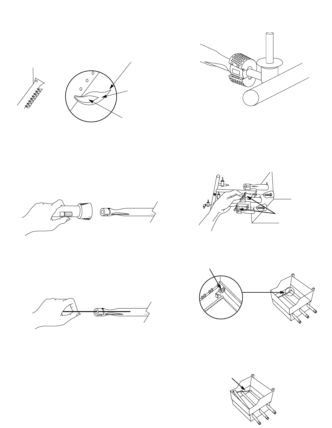
Main Burner Flame Pattern
The Weber Gas Barbecue burners have been factory set
for the correct air and gas mixture. The correct flame
pattern is shown in Figure 10.
If the flames do not appear to be uniform the length of the
burner tube, follow the burner cleaning procedures.
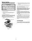
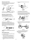
Main Burner Cleaning Procedure
Turn off the gas supply. Remove the manifold.
(See Section “Replacing the main burners”.)
Look inside each burner with a flashlight. Figure 11.
Clean the inside of the burners with a wire
(a straightened out coat hanger will work). Figure 12.
Check and clean the air shutter opening at the ends of
the burners. Check and clean the valve orifices at the
base of the valves. Use a brass bristle brush to clean
outside of burners. This is to make sure all the burner
ports are fully open.
ƽCAUTION: Do not enlarge the burner ports when
cleaning.
Replacing Main Burners
a) Your Weber Gas Barbecue must be OFF and cool.
b) Turn gas OFF at source.
c) Remove control panel: take off the burner control
knobs. Put your fingers under the edge of the
control panel at the control panel push-in buttons
and pull toward you. Lift off the control panel.
d) Use a 3/4 inch wrench to unscrew the flare nut on
the barbecue gas supply line from the manifold
fitting.
Burner inside
cooking box Tips occasionally yellowish
Light blue
Dark blue
Flames
Figure 11
Figure 12
) Lift and twist the burner assembly slightly, to
separate the crossover tube from the burners.
Figure 16. Remove the burners from the
cooking box.
Crossover tube
Figure 16
Figure 10