31
Please Do Not Return This Product To The Store. Call Us Directly! Our Trained Technicians Will Answer Your Questions and/or Ship Any Parts You May Need.
You can reach us Toll Free at 1-888-827-3667 for Consumer Assistance or online at www.wayne-dalton.com
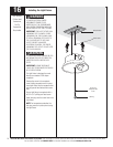
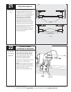
Lock Arm Installation
(Continued)
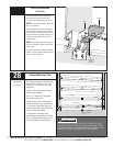
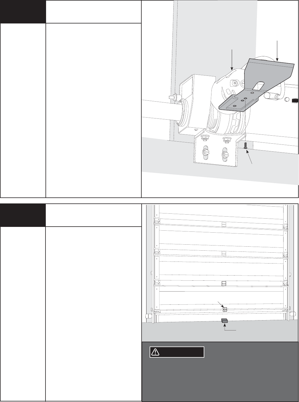
Once track radius has been determined,
secure the lock arm to the motor with
(1) 5mm x .8mm phillips pan head screw.
NOTE: If unsure of track radius, begin with
lock arm in position 1.
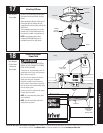
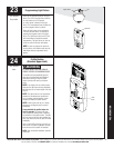
After assembly of the lock arm, manually
raise and lower the door and verify that the
lock arm does not interfere with the door. If
there is interference between the door and
the lock arm, see Page 42
for lock arm
troubleshooting.
NOTE: Do not operate the door or opener if
there is interference between the lock arm
and the door.
Reconnect the door to the motor operated
position. Activate a motor operated up/down
cycle to confirm clearance.
Lock Arm
Motor
5mm x 8mm
Phillips
Pan Screw
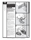
Contact Obstruction Test
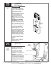
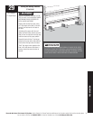
After installing the opener, the door must
reverse when it contacts a 1-1/2” high
object (or a 2 x 4 board laid flat) on the
garage floor.
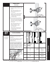
Using the wall station, activate the door
to the fully open position.
Place a 2 x 4 board flat on the garage
floor, under the door path.
Activate the door to the closed position
with the wall station. Upon contacting the
2 x 4 board, the door should stop, then
reverse direction within two seconds and
travel to the full open position.
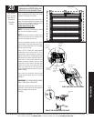
If the door does not respond to the
required tests, repeat profile routine Step
24 or 25, making sure the door is in the
fully closed position prior to activation.
Center Of Door
2 x 4 Laid Flat
On Floor
WARNING
Tools Needed:
2 x 4 Board
IF OPENER DOES NOT RESPOND PROPERLY TO THESE TESTS (STEPS
28 AND 29), DO NOT USE DOOR UNTIL A QUALIFIED SERVICE PERSON
HAS MADE NECESSARY ADJUSTMENTS/REPAIRS, OR SEVERE OR FATAL
INJURY COULD RESULT FROM OPERATING THE DOOR/OPENER.
28


