


– 95 –
No.
Part name
Compressor
Compressor lead
(Continued)
Procedure
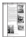
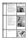
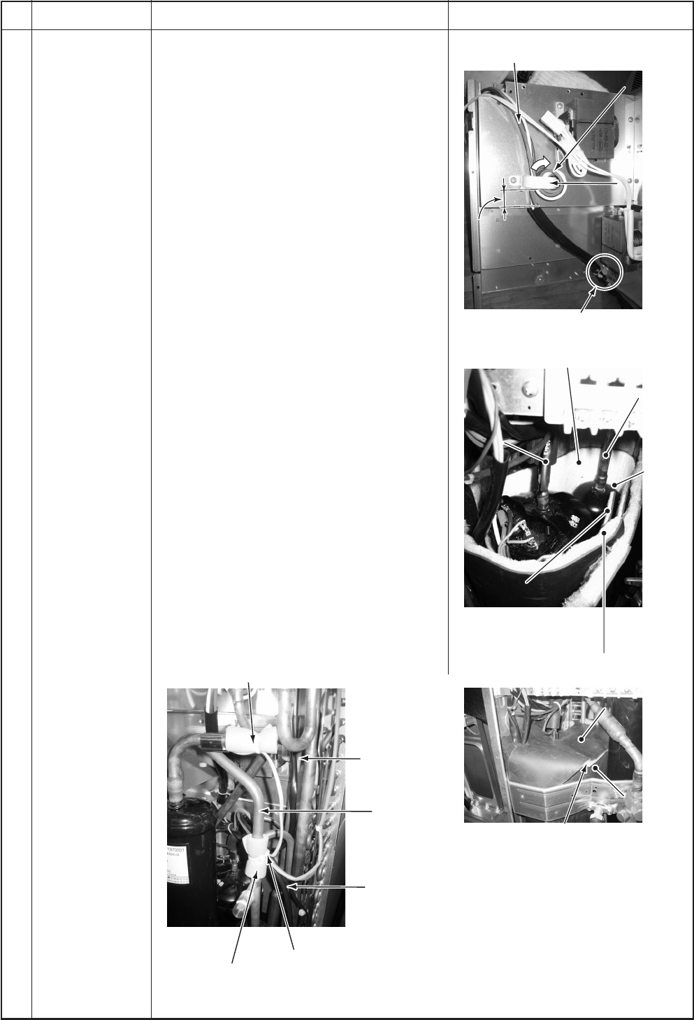
2. Mounting of compressor
1) Mount the compressor in the reverse
procedure of removal.
NOTES:
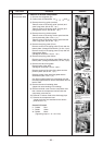
∗ After exchange of the compressor, be sure to
exchange the compressor lead. (Repair part
code of compressor lead: 43160591)
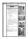
In this time, wrap the ferrite core with the
compressor lead wire by 4 times.
Using bundling band on the market, bind the
compressor lead. As the compressor lead is
long, be sure that the compressor lead does
not contact with the discharge pipe.
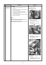
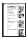
∗ Fix the removed each sensor and PMV coil
lead wire to the discharge pipe and the
suction pipe with the bundling band via the
pipe cover.
In this time, take note that each sensor and
PMV coil lead wire do not come to contact
with the discharge pipe and the reactor.
(For fixing to the discharge pipe, use the black
heat-proof pipe cover and the bundling band
for heat-proof which is sold on the market.)
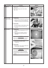
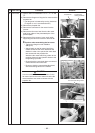
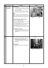
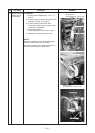
∗ As shown in the right figure, mount the
sound-insulation plate (inner side, outer side)
by inserting between the compressor and the
piping, and between piping and the partition
plate.
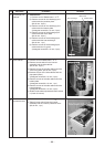
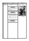
∗ Put the compressor lead wire and the
compressor case thermo between inner side
and outer side of the sound-insulation as if
dropping them in.
Remarks
Pipe cover, bundling band,
each sensor (TL, TO, TE, TS sensor)
PMV coil lead
Pipe cover, bundling band, TS sensor
Discharge pipe
Suction pipe
PMV coil lead
Set each sensor so that it does not
come to contact with the discharge pipe.
Compressor lead
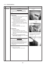
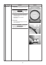
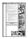
Pass the soundproof plate (outer winding)
Pass the soundproof plate (outer winding)
through between the suction pipe and
through between the suction pipe and
the accumulator.
the accumulator.
Do not make clearance between
the sound-insulation plate (upper) and
the sound-insulation plate (outer side).
Put the sound
-insulation
plate (outer side)
on the other side at this position.
Sound-insulation plate
Sound-insulation plate
(upper)
(upper)
Sound-insulation
Sound-insulation
plate (outer side)
plate (outer side)
Sound-insulation plate
(upper)
Sound-insulation
plate (outer side)
Accumulator
Accumulator
Using the bundling band on the market,
fix the bundle at 2 positions.
Wind the ferrite core
Wind the ferrite core
with the compressor
with the compressor
lead wire by 4 times.
lead wire by 4 times.
0 to 2
0 to 2”
(0 to 50mm)
(0 to 50mm)
(Positioning standard of
(Positioning standard of
compressor lead wire)
compressor lead wire)
0 to 2” (0 to 50mm)
(Positioning standard of
compressor lead wire)
Ferrite core
Ferrite core
Ferrite core
Wind the ferrite core
with the compressor
lead wire by 4 times.
Suction pipe
Suction pipe
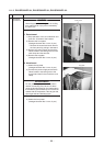
Pass the sound-insulation plate (outer side)
through between the suction pipe and
the accumulator.
Accumulator
Discharge pipe
Discharge pipe
Discharge pipe
Suction pipe
Pass the sound-insulation
Pass the sound-insulation
plate (inner side) through
plate (inner side) through
between compressor and
between compressor and
discharge pipe, suction pipe
discharge pipe, suction pipe
and then put it on the other
and then put it on the other
side at this position.
side at this position.
Pass the sound-insulation
plate (inner side) through
between compressor and
discharge pipe, suction pipe
and then put it on the other
side at this position.