


– 104 –
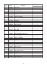
No.
Part name
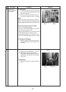
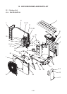
Compressor
Compressor lead
(Continued)
Procedure
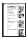
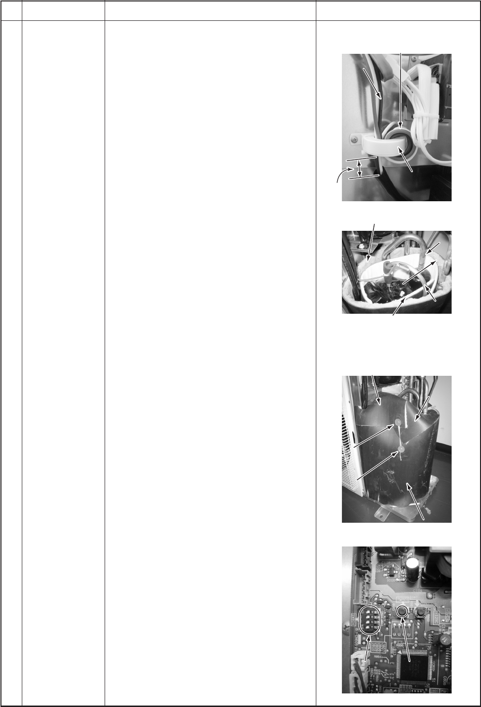
2. Mounting of compressor
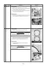
1) Mount the compressor in the reverse
procedure for removal.
NOTE :
• After replacement of the compressor, be sure
to replace the compressor lead. (Repair part
code of compressor lead: 43160591)
In this time, wrap the ferrite core with the
compressor lead wire by 4 times.
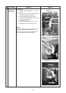
• As shown in the right figure, mount the sound-
insulation plate (inner side, outer side) by
passing through it between the compressor
and the piping, and between the piping and
the partition board.
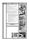
• Fix TD sensor by the bundling band for heat-
proof on the market via the pipe cover so that
TD sensor does not directly come to contact
with the discharge pipe.
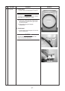
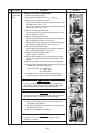
3. Vacuuming
1) Connect the vacuum pump to the charge
port and the check joint of the gas pipe
valve and then drive the vacuum pump.
2) Carry out vacuuming until the vacuum low
pressure gauge indicates 1 (mmHg).
NOTE :
Before vacuuming, open PMV fully.
If PMV is closed, vacuum may be impossible
between liquid pipe valve and PMV of the
outdoor unit.
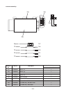
Forced full-opening method of PMV
• Turn on the leakage breaker.
• Turn on 1 and 3 of Dip switch SW804 on the
control P.C. board of the outdoor unit.
• Keep pushing SW801 on the control P.C. board
of the outdoor unit for 1 second or more.
• After pushing SW801 for 1 second or more,
turn off the leakage breaker within 2 minutes.
4. Refrigerant charge
1) Add the refrigerant amount determined by
the pipe length from the charge port of the
valve.
Remarks
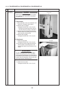
Wrap the ferrite core with
the compressor lead wire for 4 times.
Ferrite core
Ferrite core
Put the end of sound-insulation plate
(outer side) on the other end at
this position.
Compressor lead
Compressor lead
Ferrite core
0 to 2
0 to 2”
(0 to 50 mm)
(0 to 50 mm)
(Compressor lead positioning standard)
(Compressor lead positioning standard)
0 to 2” (0 to 50 mm)
(Compressor lead positioning standard)
Compressor lead
Discharge pipe
Discharge pipe
Pass through sound-insulation plate (inner side)
between compressor and discharge pipe,
suction pipe and then put the end of sound-
insulation plate on the other end at this position
Suction pipe
Suction pipe
Pass through sound-
Pass through sound-
insulation plate (outer side)
insulation plate (outer side)
between suction pipe
between suction pipe
and header pipe.
and header pipe.
Pass through sound-
insulation plate (outer side)
between suction pipe
and header pipe.
Discharge pipe
Suction pipe
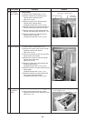
There should be no clearance between
sound-insulation plate (upper) and
sound-insulation plate (outer side).
Sound-insulation
Sound-insulation
plate (upper)
plate (upper)
Cultural rivet
Cultural rivet
Insert one side
Insert one side
under cultural rivet.
under cultural rivet.
Sound-insulation
plate (upper)
Cultural rivet
Insert one side
under cultural rivet.
Sound-insulation plate
Sound-insulation plate
(outer side)
(outer side)
Sound-insulation plate
(outer side)
SW804
SW804
SW801
SW801
SW804 SW801