


– 84 –
No.
Part name
Inverter
assembly
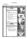
Procedure
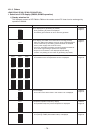
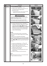
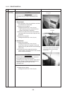
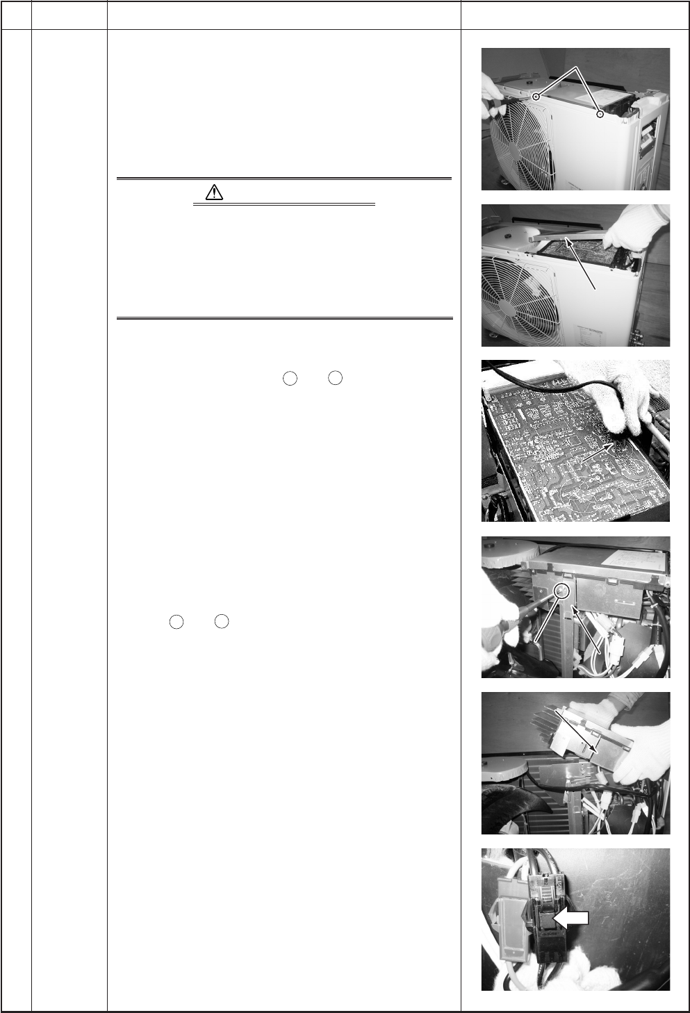
1. Turn off the power supply.
1) Perform work of Detachment 1 of
.
2) Take off screws, which fix the upper part of the
front cabinet and the inverter cover.
(M4, 8 mm, 2 pcs.)
• If removing the inverter cover under the above
condition, P.C. board can be checked.
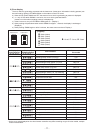
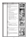
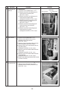
ELECTRIC SHOCK
The control circuits (including each sensor circuit
and 5V, 12V of PMV circuit, etc.) of this control P.C.
board are high-voltage circuits.
Before work, be sure to turn off the power supply.
Take sufficient care to an electric shock on the
control circuits and the conductive parts of their parts.
3) Using the discharging resistor (100Ω/40W or
equivalent) or plug of the soldering iron, electrify
continuously between
+
and
–
poles of the
electrolytic capacitor of 3 phases: C10, 11 and single
phase: C12, 13, 14 (“CAUTION HIGH VOLTAGE” is
printed) on P.C. board, and then discharge power.
For the products that the rear side are coated,
perform normal discharge.
NOTES:
According to the trouble condition, the electrolytic
capacitor may not normally discharge and the voltage
may remain.
Therefore be sure to discharge the capacitor.
As the electrolytic capacitor is one with a large capacity,
never use a screwdriver and others for short-circuiting
between
+
and
–
electrodes for discharging; otherwise
it is very dangerous because a large electric spark will
generate.
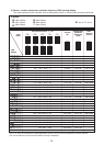
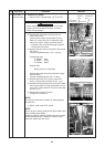
4) Perform works Detachment 1 of
and
.
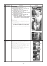
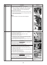
5) Take off fixing screw between the partition plate
and the inverter box. (M4, 8 mm, 1 pc.)
6) Remove various lead wires from the holder at
upper part of the inverter box.
7) Pull the inverter box upward.
In this time, cut the bundling bands which bind
each lead wire.
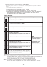
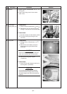
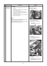
8) Remove connectors of various lead wires.
NOTE:
When removing the connectors, do not hold lead wires
by hands, but hold the connectors.
Remarks
Screws
Screws
Front
Front
cabinet
cabinet
Inverter cover
Inverter cover
Plug of soldering iron
Plug of soldering iron
Discharging position
Discharging position
(Discharging period
(Discharging period
10 seconds or more)
10 seconds or more)
Screws
Front
cabinet
Inverter cover
Plug of soldering iron
Discharging position
(Discharging period
10 seconds or more)
Fixed screw
Fixed screw
Partition plate
Partition plate
Inverter assembly
Inverter assembly
Remove the connectors
Remove the connectors
with locking function by
with locking function by
pushing the part indicated
pushing the part indicated
by the arrow mark.
by the arrow mark.
Fixed screw
Partition plate
Inverter assembly
Remove the connectors
with locking function by
pushing the part indicated
by the arrow mark.