


– 19 –
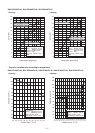
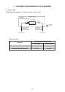
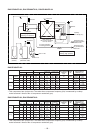
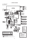
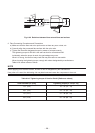
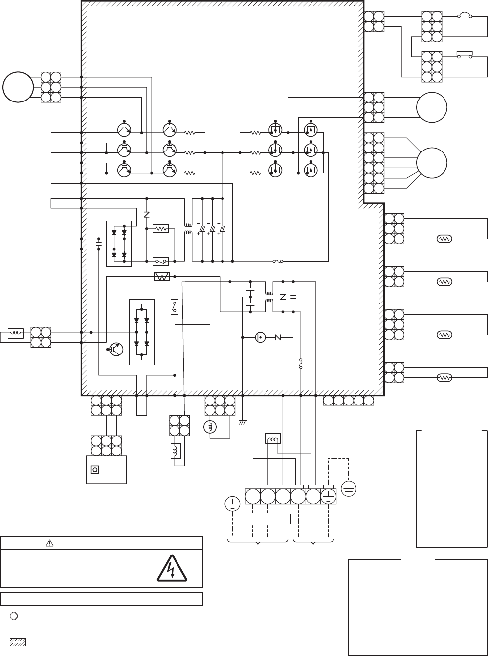
4. WIRING DIAGRAM
4-1. Outdoor Unit
RAV-SP180AT2-UL
Color
Identification
BLK : BLACK
BLU : BLUE
RED : RED
GRY : GRAY
PNK : PINK
GRN : GREEN
WHI : WHITE
BRN : BROWN
ORN : ORANGE
YEL : YELLOW
PUR : PURPLE
NOTE
CM : Compressor
PMV : Pulse Motor Valve
FM : Fan Motor
TE : Heat Exchanger Temp. Sensor
TD : Discharge Temp. Sensor
TO : Outdoor Temp. Sensor
TS : Suction Temp. Sensor
IGBT : Insulated Gate Bipolar Transistor
DB : Rectifier
CT : Curreut Transformer
49C : Compressor Case Thermostat
HP SW : High pressure switch
CAUTION : HIGH VOLTAGE
The high voltage circuit is incorporated.
Be careful to do the check service, as the
electric shock may be caused in case of
touching parts on the P.C. board by hand.
The 4-way valve coil is turned on while the cooling operation
Varistor
Varistor
L1
For optional
P.C. Board
P.C. Board
(MCC-5009)
P34
P35
P18
P19
P08
P11
P32 CN701
WHI
RED
WHI
P31 P30
BLK
ORN
BLK
WHI
P7 P03 P10 P02 CN806P33
P20
P21
P22
P23
P24
P25
YEL
YEL
BRN
YEL
ORN
DB01
DB02
Relay
Q404
Q200~205
IGBT
Q300~305
MOS-FET
R221
RED
Compressor
WHI
BLK
P04
P05
P06
2
1
2
3 3
1
1
2
1
2
2
3
2
1 1
3
5
6
4 4
6
2
3
2
1 1
3
2
3
1 1
2 2
1 1
3
2
3
1 1
3
CM
CN300
CN700
CN603
CN602
CN601
CN600
CN500
BLK
WHI
ORN
49C
BLK
RED
Fan motor
FM
Pulse
motor valve
PMV
HP SW
R220
R219
L03 C13
C12
C14
R321
R320
R319
Surge
absorber
F03
Fuse, T3.15A
AC250V
F01
Fuse, T25A
AC250V
Power
relay
Reactor
Reactor
CT
1
2
1
2
1
1 2 3 4 5
2
1
2
1
1
3
S
L2L1L2L1
3
2
2
1
1
3
3
Reactor
TS
(Suction pipe temp. sensor)
TD
(Discharge pipe temp. sensor)
TO
(Outdoor temp. sensor)
TE
(Condenser pipe temp. sensor)
1
1
2
2
Coil for
4-way valve
To indoor Power supply
208/230-1-60
CN605
BLK
SW802
MCC-1530
Sub P.C. Board
RED
PUR
GRN/YEL
WHI
BLK
2
2
1
1
3
3
3
1 1
3
3
1 1
3
High voltage
1. indicates the terminal block.
Alphanumeric characters in the cycle indicate the terminal No.
2. The two-dot chain line indicates the wiring procured locally.
3. indicates the P.C. board.
4. For the indoor unit circuit, refer to the wiring diagram of the indoor unit.