


– 21 –
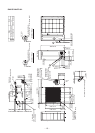
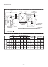
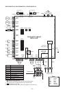
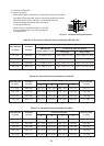
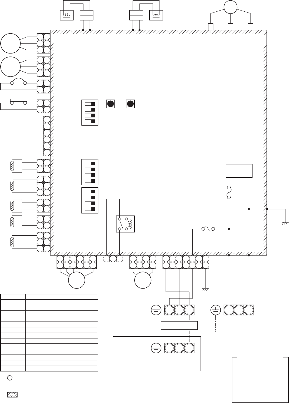
RAV-SP300AT2-UL, RAV-SP360AT2-UL, RAV-SP420AT2-UL
Color
Identification
BLK : BLACK
BLU : BLUE
RED : RED
GRY : GRAY
WHI : WHITE
YEL : YELLOW
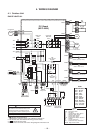
Control P.C. Board
MCC-1570
(GRY) (GRY) (WHI) U(WHI)
CN400
(WHI)
P04 P05 P06 P07
P09
P02P01
CN201 CN202CN200
49C
TL
(RED) (WHI) (BLK)
(BLK)
(RED) (WHI)
(GRY)
(WHI)
(RED)
(BLK)
Reactor
Reactor
1 1
1 1
2 2
2 2
1 1
2 2
1
2
3
4
5
6
1 1
2 2
33
TO
1 1
2 2
TE
1 1
2 2
TD
1 1
2
3 3
TS
1 1
2
1 2 3 4 5 6
1 2 3
1 3
4
1 4
1 4
1 7
716
3 3
V W
CM
L/F
FM01
CN300
(WHI)
CN609
(BLU)
CN690
(RED)
CN610
(YEL)
CN604
(WHI)
CN603
(WHI)
CN602
(YEL)
CN601
(WHI)
CN600
(WHI)
CN710
(WHI)
CN704
(BLU)
RY704
SW802
SW803
1
ON
CN701
(WHI)
CN04
(WHI)
1 1
2 2
33
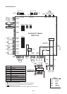
Fuse, F03
T10A, 250V~
Fuse, F01
T25A, 250V~
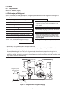
L1 L2L1 L2 S
L1 L2 S
Outdoor unit
Indoor unit
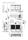
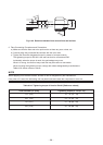
1. indicates the terminal block.
Alphanumeric characters in the cycle indicate the terminal No.
2. The two-dot chain line indicates the wiring procured locally.
3. indicates the P.C. board.
4. For the indoor unit circuit, refer to the wiring diagram of the indoor unit.
Earth
screw
Power supply
208/230-1-60
Earth
screw
Earth
screw
3 5
53
20SFPMW
FM02
2 3 41
ON
2 3 4
SW804 SW801 SW800
1
ON
2 3 4
HP SW
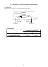
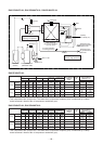
Symbol
CM
FM01, 02
PMV
TD
TS
TE
TL
TO
20SF
49C
HP SW
RY
L/F
Parts name
Compressor
Fan Motor
Pulse Motor Valve
Pipe temp. sensor (Discharge)
Pipe temp. sensor (Suction)
Heat exchanger sensor 1
Heat exchanger sensor 2
Outside temp. sensor
4-way valve coil
Compressor case thermostat
High pressure switch
Relay
Line Filter
High voltage