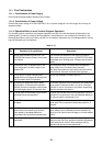
– 99 –
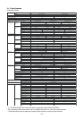
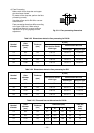
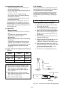
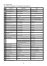
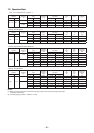
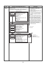
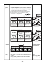
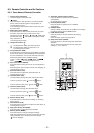
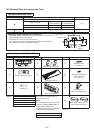
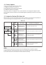
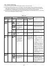
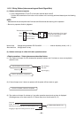
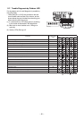
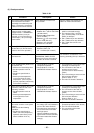
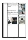
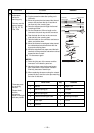
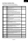
No. Checking procedurePart name
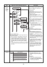
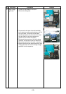
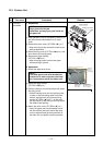
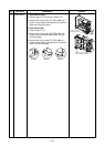
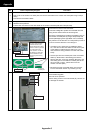
Outdoor temperature sensor
(TO), discharge temperature
sensor (TD), suction
temperature sensor (TS),
outdoor heat exchanger
temperature sensor (TE),
A room gas side temperature
sensor (TGa), B room gas
side temerature sensor (TGb)
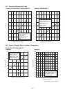
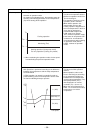
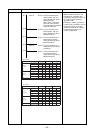
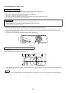
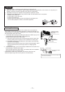
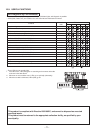
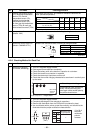
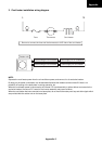
5 Disconnect the connector, and measure resistance value with the
tester. (Normal temperature)
6
COM
COM
254
Y
W
BR BL
1
R
6
O
3
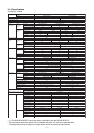
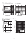
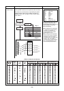
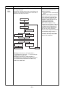
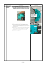
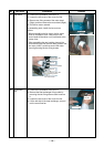
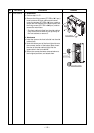
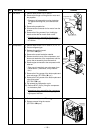
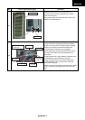
Measure the resistance value of winding by using the tester.
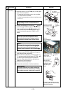
Measure the resistance value of winding by using the tester.
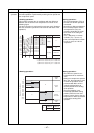
4-way valve coil
(Model : VHV)
Electronic control valve coil
(Model : CAM-MD12TF-1)
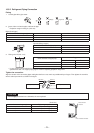
7
Position
Red - White
White - Orange
Brown- Yellow
Brown- Blue
Resistance value
1435±144 Ω
Under 20°C
Resistance value
42 to 50kΩ
42 to 50kΩ
42 to 50kΩ
42 to 50kΩ
Under 20°C
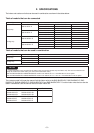
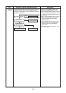
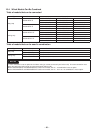
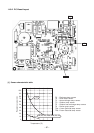
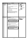
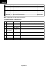
10°C 20°C 30°C 40°C 50°C
100 64 41 27 18
20.6 12.6 10.0 5.1 3.4
20.5 12.5 10.0 5.3 3.6
Temperature
Sensor
TD (kΩ)
TGa, TGb (Cooling only)
TO, TE, TS (kΩ)
TGa, TGb (Heat Pump) (kΩ)
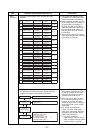
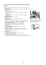
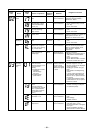
No.
1
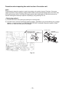
MCC-5009
Soldered
surface
Heat sink IGBT side
C12 C13 C14
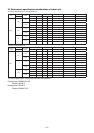
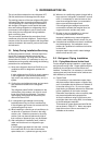
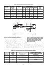
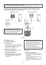
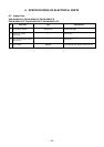
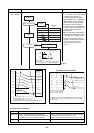
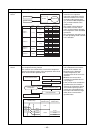
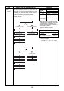
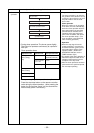
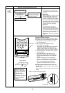
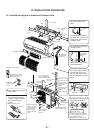
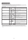
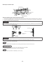
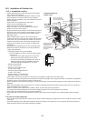
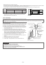
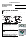
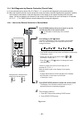
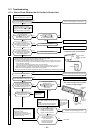
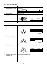
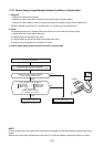
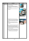
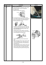
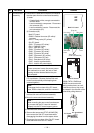
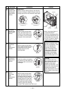
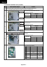
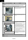
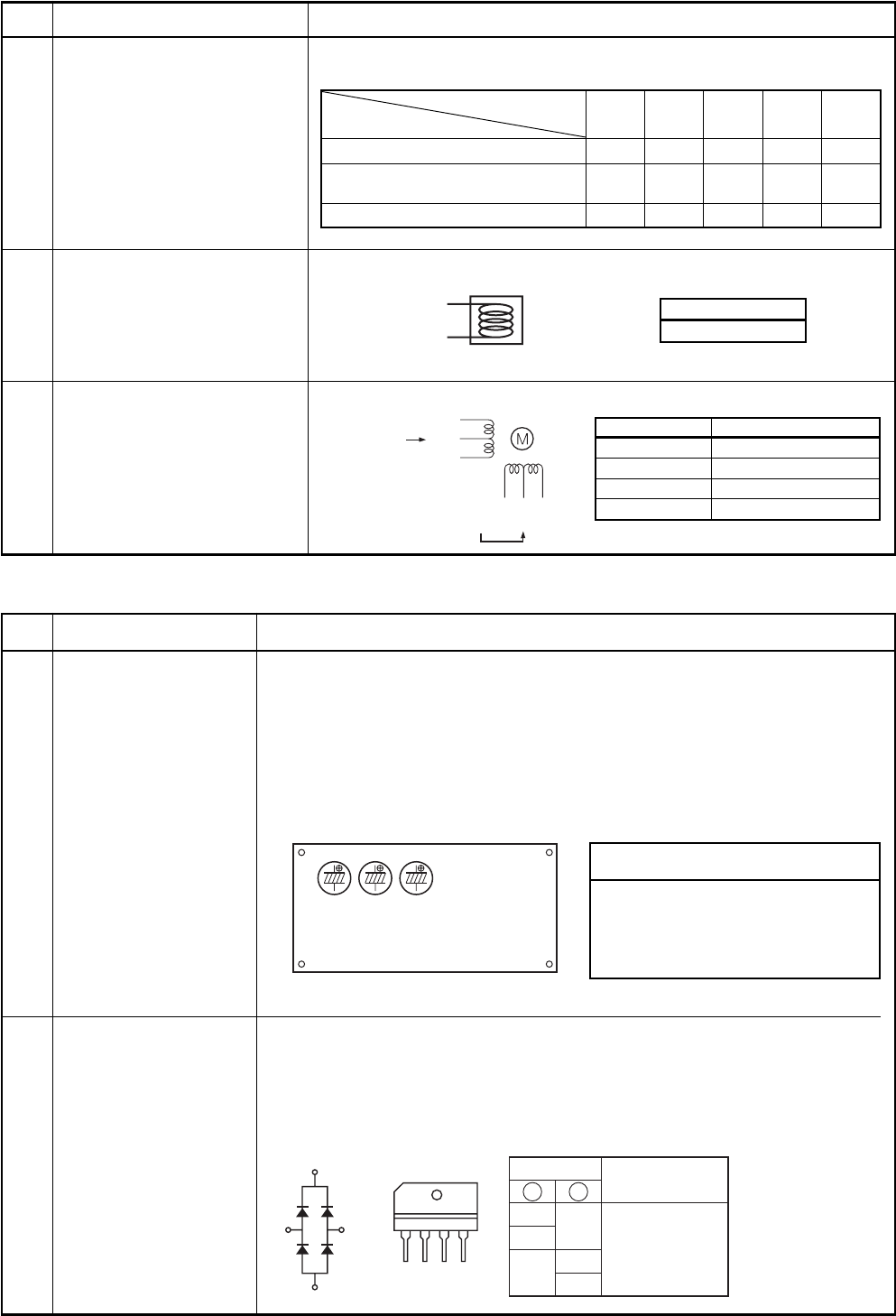
11-9-5. Checking Method for Each Part
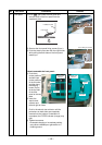
Part name
Electrolytic capacitor
(For boost, smoothing)
Checking procedure
1. Turn OFF the power supply breaker.
2. Discharge all three capacitors completely.
3. Check that safety valve at the bottom of capacitor is not broken.
4. Check that vessel is not swollen or exploded.
5. Check that electrolytic liquid does not blow off.
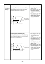
6. Check that the normal charging characteristics are shown in continuity test
by the tester.
Case that product is good
Pointer swings once, and returns
slowly. When performing test
once again under another polarity,
the pointer should return.
C12, C13, C14 → 760µF/400V
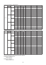
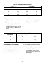
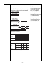
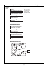
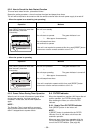
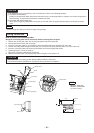
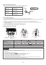
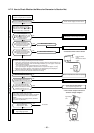
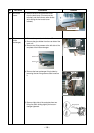
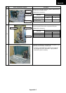
1. Turn OFF the power supply breaker.
2. Completely discharge the four electrolytic capacitors.
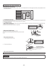
3. Remove the diode block from the PCB (which is soldered in place).
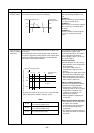
4. Use a multimeter with a pointer to test the continuity, and check that the
diode block has the proper rectification characteristics.
Diode block
2
Resistance value
in good product
∞
Tester rod
+ –
–
~
~~
~
+–~
2
3
4
1
123
(DBO1)
4
4
23
~
2
1
~
3
~
+
+
–
10 to 20 Ω
when the
multimeter
probe is
reversed