


– 70 –
10-5. Installation of Outdoor Unit
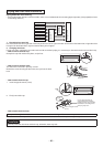
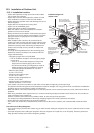
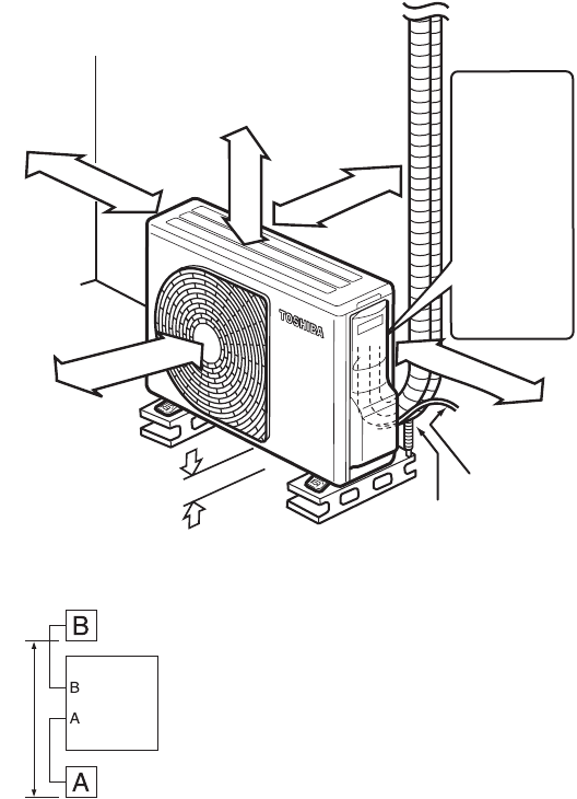
10-5-1. Installation Location
A place which provides enough space around the outdoor
unit as shown in the diagram.
A place which can bear the weight of the outdoor unit and
does not allow an increase in noise level and vibration.
A place where the operation noise and discharged air do not
disturb neighbors.
A place which is not exposed to a strong wind.
A place free of combustible gases.
A place which does not block a passageway.
When the outdoor unit is to be installed in an elevated
position, be sure to secure its feet.
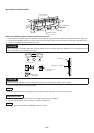
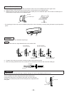
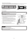
Piping connections to the outdoor unit should be arranged in
the sequence A, then B, starting from the bottom. (For each
piping connection, the gas pipe is on the bottom and the
liquid pipe on top.)
When multiple indoor units are to be connected to the
outdoor unit, make sure the ends of the pipes and wires from
each indoor unit are connected to the outdoor unit correctly.
(Problems caused by indoor units being connected to the
outdoor unit incorrectly are very common in multiple-unit
installations.)
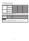
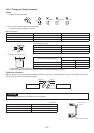
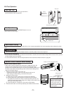
The length and height differences of the connecting pipes,
between the indoor and outdoor units, must be within the
ranges indicated below.
Total piping length: Two room (A+B) Multi
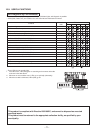
This air conditioner accepts a connection piping length
of up to 30 m.
There is no need to add refrigerant as long as the
length of the connection piping is 20 m or less.
You will need to add 20 g of refrigerant per meter of
added connection piping for installations requiring
connection piping to be between 21 m to 30 m.
Minimum piping length:
A or B = 2 m or more
Maximum indoor piping length:
A or B = 20 m or less
Maximum piping height difference:
A or B = 10 m or less
Maximum piping / height difference
between two rooms = 10 m or less
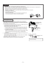
If the outdoor unit is to be mounted on a wall, make sure the platform supporting it is sturdy enough.
The platform should be designed and manufactured to maintain its strength over a long period of time, and sufficient consideration
should be given to ensuring that the outdoor unit will not fall.
When the outdoor unit is to be mounted high on a wall, take particular care to ensure that parts do not fall, and that the installer is
protected.
When doing installation work at ground level, it is usual to make wiring and pipe connections to the indoor units, first, and then to
make connections to the outdoor unit.
However, if outdoor work is difficult it is possible, instead, to make changes to the procedure.
For example, by making adjustments to the wiring and piping lengths on the inside (rather than the outside).
A place where the drain water does not cause any problems.
The outdoor unit should not be installed with one indoor unit only. Be sure the (outdoor) unit is installed with at least two indoor
units.
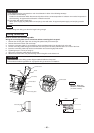
Precautions for Adding Refrigerant
Use a scale having a precision with at least 10 g per index line when adding the refrigerant. Do not use a bathroom scale or similar
instrument.
Use liquid refrigerant when refilling the refrigerant. Since the refrigerant is in liquid form, it can fill quickly. Therefore, perform the
filling operation carefully and insert the refrigerant gradually.
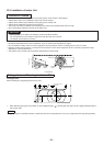
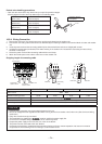
100 mm or
more from
wall
Extension drain hose
(Option: RB–821SW)
80 mm or more only
when unobstructed to
the front and both sides
250 mm or
more from wall
200 mm or more
50 mm or more
from wall
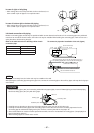
In principle,
leave open
When installing the
outdoor unit, leave open
in at least two of
directions (A), (B), (C)
and (D) shown in the
right figure.
Ensure sufficient space
to allow drainage
(A)
(B)
(C)
(D)
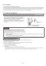
power cord
As shown in the
figure, position
power cord and
connecting
cable
downward, and
lead out along
piping
connection port.
Installation diagram of
outdoor units
10 m or less
Outdoor
unit
•
•
•
•
•
•
•
•
•
•
•
•
•
•
•
•
•
•
•
•
•
•
•
•
•