


– 78 –
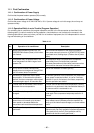
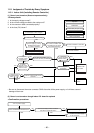
11. HOW TO DIAGNOSE THE TROUBLE
The pulse motor circuits are mounted to both indoor
and outdoor units. Therefore, diagnose troubles
according to the trouble diagnosis procedure as
described below. (Refer to the check points in
servicing written on the wiring diagrams attached to
the indoor/outdoor units.)
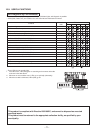
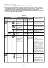
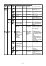
No.
1
2
3
4
5
6
Troubleshooting Procedure
First Confirmation
Primary Judgment
Judgment by Flashing LED of Indoor Unit
Self-Diagnosis by Remote Controller
Judgment of Trouble by Every Symptom
How to Check Simply the Main Parts
Page
80
81
81
82
85
95
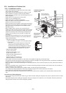
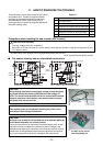
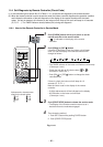
Precautions when handling the new inverter (3DV Inverter)
! CAUTION: HIGH VOLTAGE
The high voltage circuit is incorporated.
Be careful to do the check service, as the electric shock may be caused in case of touching parts on the
P.C. board by hand.
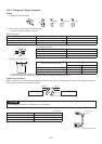
The new inverter (3DV inverter) will be incorporated starting with this unit.
(3DV: 3-shunt Discrete Vector control)
! !
! !
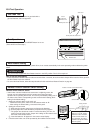
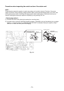
! The control circuitry has an uninsulated construction.
MCU
G-Tr
FET(6in1)
IGBT x 6
FET x 6
MCU
Separate
potential
Photocoupler
Photocoupler
Compressor
Compressor
Fan motor
Fan motor
Hall device
M18YAV-E, M18YACV-E (insulated type) EAV-E, EACV-E series (uninsulated type)
Shared
potential
Driver
Driver
Amplifier
Amplifier
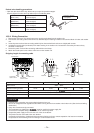
CAUTION!!
A high voltage (equivalent to the supply voltage) is also energized
to ground through the sensors, PMV and other low-voltage cir-
cuits. The sensor leads and other wires are covered with insulated
tubes for protection. Nevertheless, care must be taken to ensure
that these wires are not pinched.
CAUTION!!
Take sufficient care to avoid directly touching any of the circuit
parts without first turning off the power.
Sensor leads
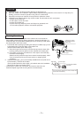
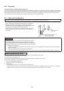
Do NOT lay the circuit
board assembly flat.
CAUTION!!
At times such as when the circuit board is to be replaced, place the
circuit board assembly in a vertical position.
Laying the board flat on an electrically conductive object (such as the
top panel of the air conditioner's outdoor unit) while a charge is still
retained by the electrolytic capacitors of the inverter's main circuit may
cause short-circuiting between the electrolytic capacitors and second-
ary circuit components and result in damage to the components.
Table 11-1