


– 60 –
10. INSTALLATION PROCEDURE
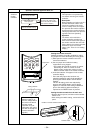
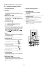
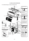
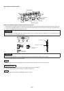
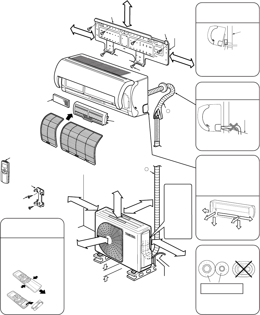
10-1.Installation Diagram of Indoor and Outdoor Units
Before installing the wireless
remote control
100 mm or
more from
wall
Insert the cushion between
the indoor unit and wall, and
tilt the indoor unit for better
installation work.
Make sure the drain hose is
sloped downward.
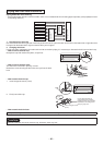
The auxiliary piping can be
connected at the left, rear
left, rear right, right, bottom
right or bottom left as shown
below.
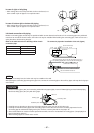
Extension drain hose
(Option: RB–821SW)
6 mm thick heat resisting
polyethylene foam
80 mm or more only
when unobstructed to
the front and both sides
Remote control holder
(Mounting holes on both
left and right sides)
Remote control
holder mounting
screw
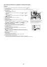
For the rear left and left
piping
Wall
Do not allow the drain hose
to become slack.
Cut the piping
hole slightly
sloped
Insulate the refrigerant pipes
separately, not together.
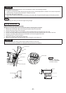
• With the remote control
cover removed, correctly
load the supplied batteries
while observing their
polarity.
Cover
Wireless remote control
Batteries
Wireless remote control
Hook
Installation
plate
Zeolite-plus filter
Plasma pure filter
Shield pipe
(for extension
drain hose)
Z
Hook
Bottom right
Rear
right
Right
Left
Bottom left
Rear left
47 mm or more
74 mm or
more
140 mm or
more
250 mm or
more from wall
200 mm or
more
50 mm or more
from wall
Mounting screw
Hook
Air filters
In principle,
leave open
As shown in the
figure, position
power cord and
connecting
cable
downward, and
lead out along
piping
connection port.
When installing the
outdoor unit, leave
open in at least two
of directions (A),
(B), (C) and (D)
shown in the right
figure.
Ensure sufficient
space to allow
drainage
(A)
(B)
(C)
(D)
power cord
Y
a
g
e
f
b
d
h
b
c
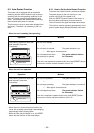
In case the piping is installed above
the ceiling, it shall be covered with
thicker insulating material
(polyethylene form, 10 mm-thick)