


– 28 –
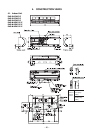
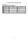
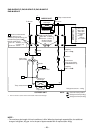
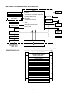
RAS-B16EKVP-E, RAS-B13EKVP-E, RAS-B10KVP-E
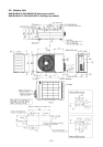
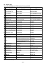
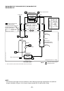
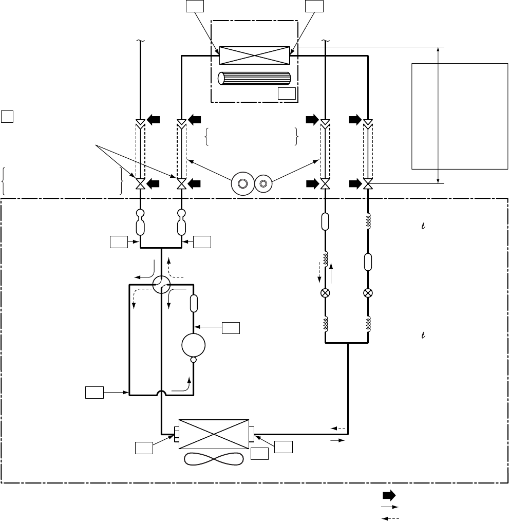
RAS-M18EAV-E
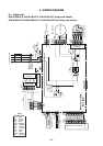
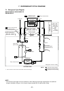
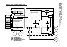
NOTE :
Gas leak check position
Refrigerant flow (Cooling)
Refrigerant flow (Heating)
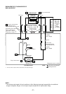
INDOOR UNIT
T1Tca
TO
Temp. measurement
To B room To B room
Indoor heat
exchanger
Deoxidized copper pipe
Both A and B rooms
Outer dia. : 6.35mm
Thickness : 0.8mm
Sectional shape
of heat insulator
Allowable height
difference : 10m
Allowable pipe length
P
Pressure measurement
Gauge attaching port
Vacuum pump connecting port
Capillary
Ø2.2 x 200
Capillary
Ø2.2 x 200
Pulse motor
valve at liquid side
(CAM-B22YGTF-2)
Td
4-way valve
(STF-0108Z)
Compressor
DA130A1F-25F
TS
T2
Outdoor heat
exchanger
Temp. measurement
Propeller fan
Refrigerant amount : 1.20kg
OUTDOOR UNIT
Muffler
Muffler
TE
Strainer
Deoxidized copper pipe
Both A and B rooms
Outer dia. : 9.52mm (10,13)
: 12.7mm (16)
Thickness : 0.8mm
Ta
Indoor fan
TGaTGb
Per 1 unit
Max.: 20m
Total: 30m
Chargeless
= 20m
Charge
= 20g/m
(21 to 30m)
*1
*1 The TC sensor is at the center of the indoor unit’s heat exchanger.
NOTE :
• The maximum pipe length of this air conditioner is 30m. When the pipe length exceeds 20m, the additional
charge of refrigerant, 20g per 1m for the part of pipe exceeded 20m is required (Max. 200g)