


– 33 –
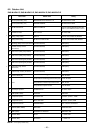
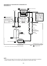
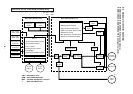
8-2. Outdoor Unit (Inverter Assembly)
RAS-M14EAV-E, RAS-M18EAV-E (Heat pump models)
RAS-M14EACV-E, RAS-M18EACV-E (Cooling-only models)
220–240 V ~50Hz
220 V ~60Hz
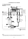
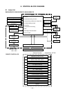
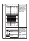
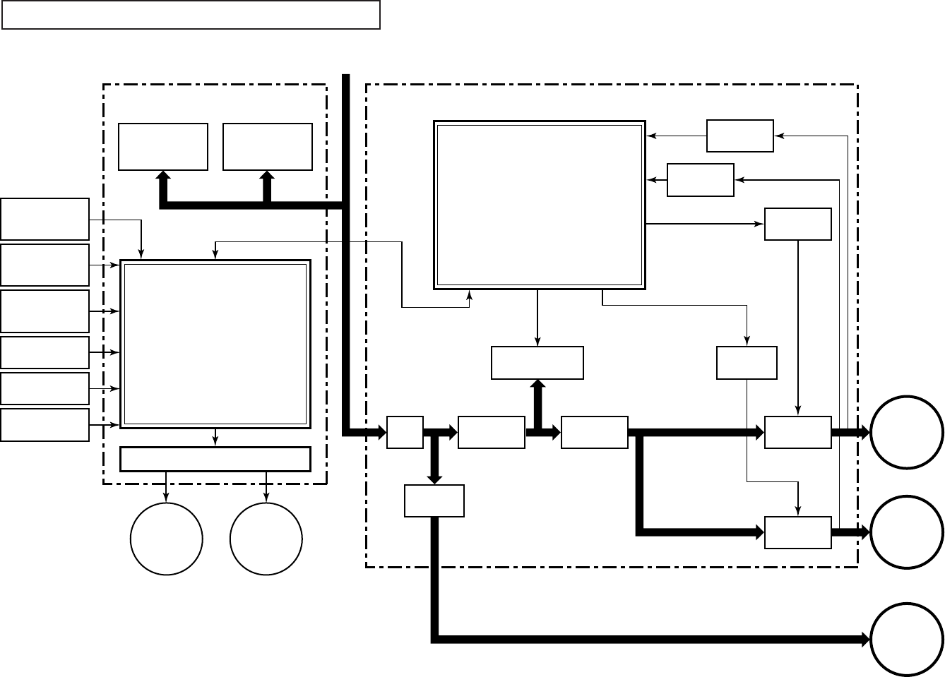
CONTROL BLOK DIAGRAM (Outdoor unit)
Driver circuit of P.M.V.
Noise
filter
Relay
RY701
Converter
(AC → DC)
Input current
sensor
4-way
valve
A unit
P.M.V.
Unit A
send/receive
circuit
Unit B
send/receive
circuit
B unit
P.M.V.
Inverter
(DC → AC)
Gate drive
circuit
Gate drive
circuit
Inverter
(DC → AC)
Outdoor
fan motor
Compressor
MCC-5015 (SUB P.C.B) MCC-5009 (SUB P.C.B)
Current
detect
Current
detect
M.C.U
•
Inverter output frequency control
• A/D converter function
• P.M.V. control
• Discharge temp. control
• Error displey
•
Signal communication to MCU
M.C.U
• PWM synthesis function
• Input current release control
• IGBT over-current detect control
• Outdoor fan control
•
High power factor correction control
• Signal communication to MCU
Gas side pipe
temp. sensor
(unit B) (TGb)
Gas side pipe
temp. sensor
(unit A) (TGa)
Outdoor Heat-
exchanger temp.
sensor (TE)
Discharge temp.
sensor (TD)
Suction temp.
sensor (TS)
Outdoor air temp.
sensor (TO)
P.M.V : Pulse Motor Valve
PWM : Pules Width Modulation
IGBT : Insulated Gate Bipolar Transistor
*1 : Heat Pump Model Only
High power factor
correction circuit
*1
*1