


– 92 –
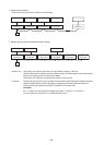
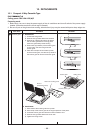
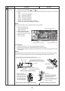
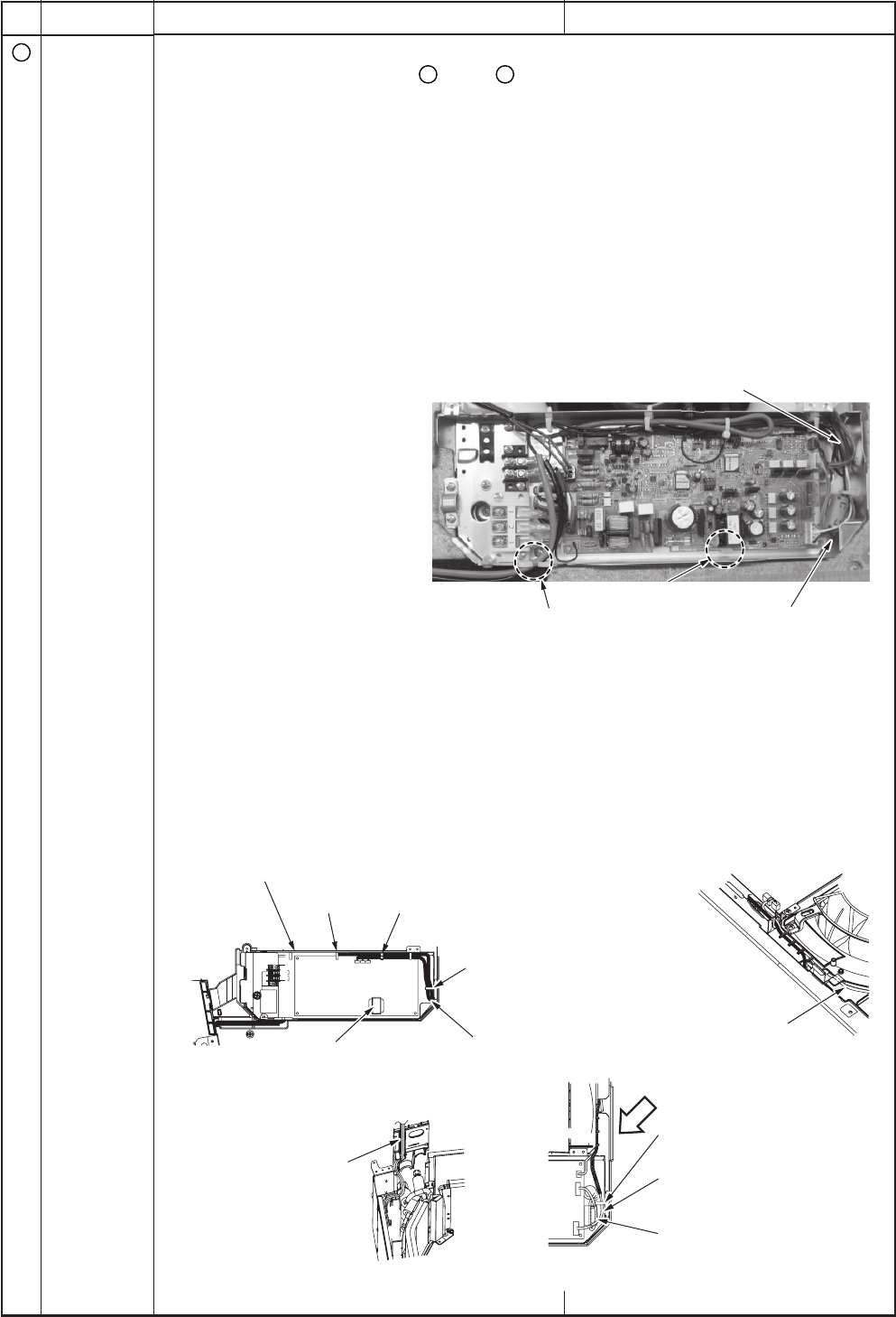
Ferrite core for sensor lead
Drawing-out port of lead wire
Card edge spacer
Card edge spacer
Ferrite core for fan motor
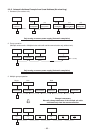
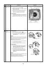
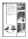
<Details of piping cover assembly and mounting>
<Details of sensor lead wire drawing>
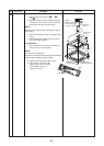
<Details of fan motor lead wire drawing>
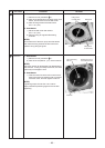
As shown in the figure,
hook the sensor lead wires
to claw of the piping cover
and then pass them so that
they are stored in the groove.
After mounting the piping
cover, check each lead wire
does not hit the liquid pipe.
Turn up the sensor lead wires
and fix surely with the cord clamp.
Fix the sensor lead wires with cord clamps (2 positions) so that
it does not slacken at P.C. board side and draw wires as shown in the figure.
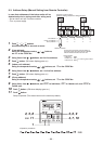
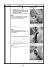
Please note the
float SW lead wires are
set at inner side of the
fan motor lead wires.
Turn up the fan motor lead wires
and fix surely with the cord clamp.
(There should be no catching of
lead wire by P.C. board.)
Clamp (yellow, gray, black) lead wires
of the fan motor and arrange them
as shown in the figure.
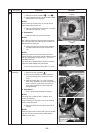
Cord clamp
Cord clamp Tighten together the shield wires of the
sensor lead wires and the remote controller.
Be careful that other sensor does not fall out.
Adhere on the
transformer.
Cord clamp
Arrow view E
E
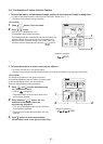
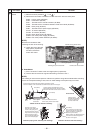
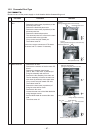
No.
6
Part name
Electric
parts box
Procedure
1. Detachment
1) Perform works of procedure
1
-1-and
2
-1.
2) Remove connectors of the lead wire connected to the following connectors of the control P.C.
board.
CN33 : Louver motor (5P, White)
CN34 : Float switch (3P, Red)
CN68 : Drain pump (3P, Blue)
CN101 : TC2 sensor (2P, Black)
CN102 : TCJ sensor (2P, Red)
CN333 : Fan motor power supply (5P, White)
CN334 : Fan motor position detection (5P, White)
NOTE)
Remove the connectors after unlocking the lock of the housing.
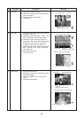
3) Remove each lead wire
from cord clamps in the
electric parts box.
4) Remove the power supply
wiring, remote controller
wiring, and crossover wiring.
5) Take off screws
(Ø4 × 10, 2 pcs.)
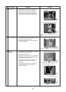
2. Attachment
1) Tighten screws (Ø4 × 10, 2 pcs.) fixing the electric parts box.
2) Connect the connectors as original before being removed in item 1.
3) Perform power supply wiring, remote controller wiring, and crossover wiring between inside
and outside.
NOTE)
For drawing of each wire and position of ferrite core, perform wiring same as those before removing.
If there is incomplete drawing of wire, short or water leakage of the parts may be caused.
Remarks