


– 66 –
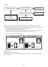
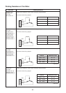
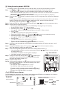
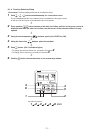
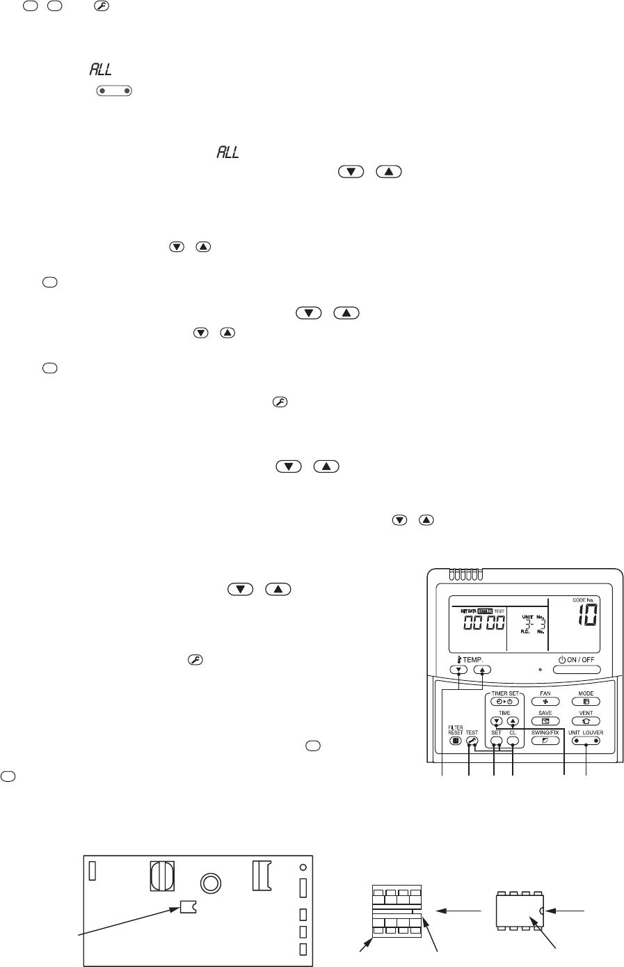
EEPROM(IC10)
Match the notched parts of IC socket and
EEPROM and then put in.
MCC-1402
EEPROM
IC socket Notch
Notch
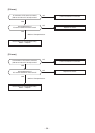
[3] Writing the setting data to EEPROM
The settings stored in the EEPROM of the P.C. board for indoor unit servicing are the factory-set values.
Step 1 Push
SET
,
CL
and
TEST
buttons on the remote controller simultaneously for more than 4 seconds.
∗ In the group control operation, the unit No. displayed for the first time is the header unit No.
At this time, the CODE No. (DN) shows “
”. Also, the fan of the indoor unit selected starts its operation
and the swing operation starts if it has the louvers.
(The unit No. “
” is displayed if the auto-address setting mode is interrupted in [2] step 2 a))
Step 2 Every time when
UNIT LOUVER
button is pushed, the indoor unit No. in the group control operation are displayed
in order.
(The settings stored in the EEPROM of the P.C. board for indoor unit servicing are the factory-set values.)
Specify the indoor unit No. with its P.C. board replaced to the P.C. board for indoor unit servicing.
(You cannot perform this operation if “
” is displayed.)
Step 3 Select the CODE No. (DN) can be selected by pushing the
/ button for the temperature setting.
Step 4 Set the indoor unit type and capacity.
The factory-set values shall be written to the EEPROM by changing the type and capacity.
1. Set the CODE No. (DN) to “
”. (without change)
2. Select the type by pushing
/ buttons for the timer setting.
(For example, 4-way Air Discharge Cassette Type is set to “0001”. Refer to table 2)
3. Push
SET
button.
(The operation completes if the setting data is displayed.)
4. Change the CODE No. (DN) to “
” by pushing / buttons for the temperature setting.
5. Select the capacity by pushing
/ buttons for the timer setting.
(For example, 80 Type is set to “0012”. Refer to table 3)
6. Push
SET
button.
(The setting completes if the setting data are displayed.)
7. Return to the normal stop status by pushing
TEST
button.
(Approx. 1 minute is needed to start operation of the remote controller.)
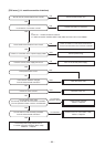
Step 5 Write the on-site setting data to the EEPROM, such as address setting, etc. Perform the steps 1 and 2
above again.
Step 6 Change the CODE No. (DN) to “
” by pushing / buttons for the temperature setting.
(this is the setting for the filter sign lighting time.)
Step 7 Check the setting data displayed at this time with the setting data put down in [1].
1. If the setting data is different, modify the setting data by pushing
/ buttons for the timer setting to
the data put down in [1].
The operation completes if the setting data is displayed.
2. If the data is the same, proceed to next step.
Step 8 Change the CODE No. (DN) by pushing
/ buttons for the
temperature setting. As described above, check the setting data
and modify to the data put down in [1].
Step 9 Repeat the steps 6 and 7.
Step 10 After the setting completes, push
TEST
button to return to the normal
stop status. (It takes approx. 1 min until the remote control opera-
tion is available again.)
∗ The CODE No. (DN) are ranged from “
” to “..”.
The CODE No. (DN) is not limited to be serial No.
Even after modifying the data wrongly and pushing
SET
button, it
is possible to return to the data before modification by pushing
CL
button if the CODE No. (DN) is not changed.
<Fig. 1 RBC-AMT32E>
<Fig. 2 EEPROM layout diagram>
The EEPROM (IC10) is attached to the IC socket. When detaching the EEPROM, use a tweezers, etc. Be sure to
attach the EEPROM by fitting its direction as shown in the figure.
∗ Do not bend
the IC lead
when replacing.
3651 42