


– 18 –
110
129
44
49
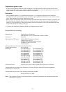
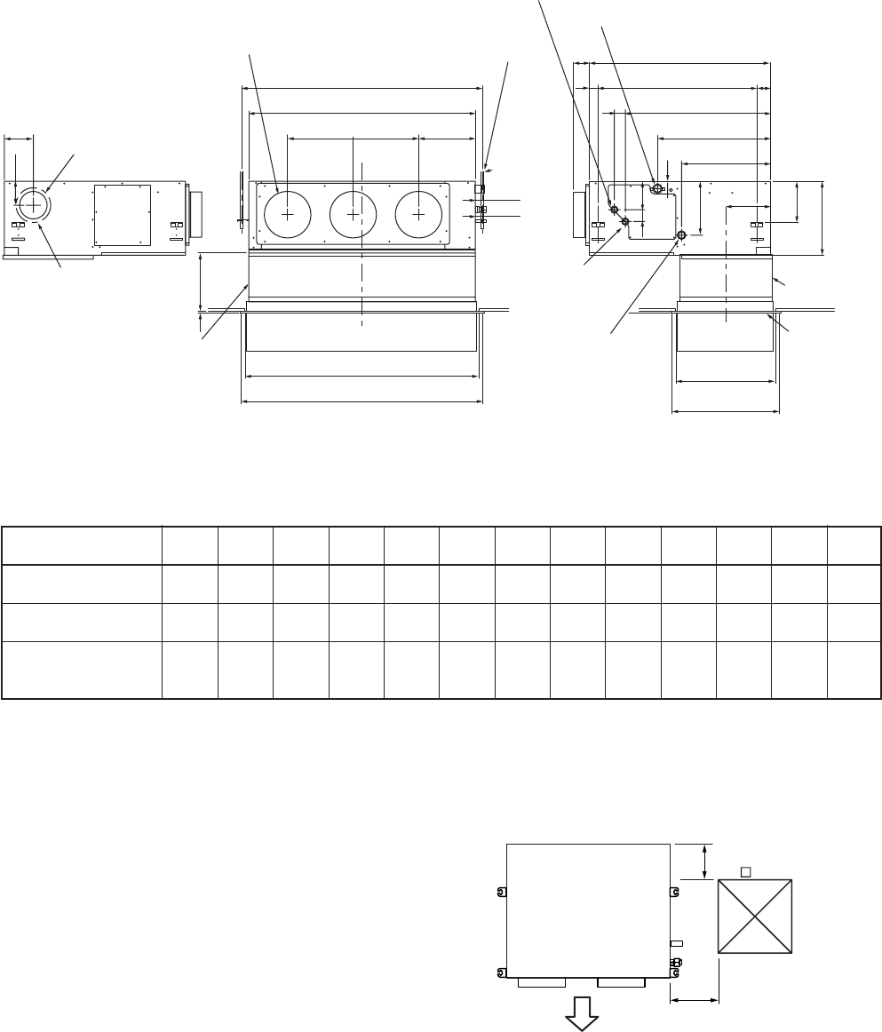
Knock-out hole Ø125
(Air take-in port)
6-Ø4 Tapping screw
undersized hole Ø160
Hanging bolt pitch 700
5941
Main unit dimension 800
75
Hanging bolt pitch B
Main unit dimension A
J = M x K H
Discharge port flange
N-Ø200
Hanging bolt
4-M10 screw
(Arranged locally)
60 to 260
9
Suction port canvas
(Separate sold)
C
Ceiling open size D
Panel external dimension E
Ceiling open size
470
Panel external
dimension 500
Panel C.L
410
Ø26 Power supply,
remote controller
cable take-out port
Refrigerant pipe
connecting port
(Liquid side ØG)
Suction port
flange
(Separate sold)
Suction port
panel
(Separate sold)
Drain pipe connecting port
for vinyl chloride pipe
(Inner dia. 32, VP. 25)
41
196
393
498
638
50
131
243
50
Refrigerant pipe connecting port
(Gas side ØF)
174
320
450
Plane view of main unit
Check port A
100
300
(Pipe side)
Discharge side
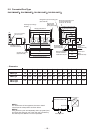
NOTE 1 :
For maintenance of the equipment, be sure to install
a check port A at the position as shown below.
NOTE 2 :
Using the drain up kit sold separately, drain-up by 300 (mm)
from drain pipe draw-out port of the main unit is necessary.
The drain-up over 300mm or more is impossible.
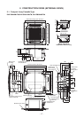
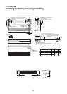
2-2. Concealed Duct Type
RAV-SM564BT
∗∗
∗∗
∗
, RAV-SM804BT
∗∗
∗∗
∗
, RAV-SM1104BT
∗∗
∗∗
∗
, RAV-SM1404BT
∗∗
∗∗
∗
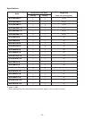
• Dimension
SM56 type
SM80 type
SM110 type
SM140 type
ABCDEFGHJKMNO
700 766 690 750 780 12.7 6.4 252 280 280 1 2 410
1000 1066 990 1050 1080 15.9 9.5 252 580 290 2 3 410
1350 1416 1340 1400 1430 15.9 9.5 252 930 310 3 4 410