


– 65 –
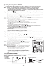
[2] P.C. Board for indoor unit servicing replacement procedures
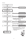
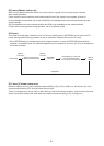
Step 1 Replace the P.C. board to the P.C. board for indoor unit servicing.
On the new P.C. board, set the same setting of the jumper wire and setting of shortcut connection
connector as those of the P.C. board before replacement.
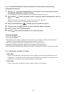
Step 2 According to the system configuration, turn on the indoor unit following to the either methods shown below.
a) Single operation (Indoor unit is used as standalone.)
Turn on the indoor unit.
1. After completion of the auto-address setting mode (required time: approx. 5 min.), proceed to [3].
(System address = 1, Indoor unit address = 1, Group address = 0 (standalone) are automatically set.)
2. Push
SET
,
CL
and
TEST
buttons simultaneously for more than 4 seconds to interrupt the auto-address
setting mode, and proceed to [3]. (The unit No. “
” is displayed.)
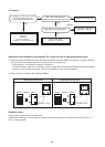
b) Group operation (including twin system)
Turn on the indoor unit(s) with its P.C. board replaced to the P.C. board for indoor unit servicing,
according to either methods 1 or 2 shown below.
1. Turn on only the indoor unit with its P.C. board replaced. (Be sure to confirm the remote controller is
surely connected. If not, the operation [3] cannot be performed.)
Perform either methods 1 or 2 described in item a) above.
2. Turn on the multiple indoor units including the indoor unit with its P.C. board replaced.
• Twin, triple, double twin, 1 system only
• All group connections
After completion of the auto-address setting mode (required time: approx. 5 min.), proceed to [3].
∗ The header unit of the group may be changed by performing the auto-address setting.
Also, the system address/Indoor unit address of the indoor unit with its P.C. board replaced may be
assigned to the addresses (not used) other than those of the indoor units without its P.C. board replaced.
It is recommended to keep the information in advance, which cooling system the indoor unit belongs to
or whether the indoor unit works as the header unit or the follower unit in the group control operation.
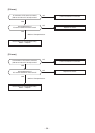
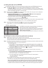
[1] Setting data read out from EEPROM
The setting data modified on the site, other than factory-set value, stored in the EEPROM shall be read out.
Step 1 Push
SET
,
CL
and
TEST
button on the remote controller simultaneously for more than 4 seconds.
∗ When the group operation control is performed, the unit No. displayed for the first time is the header unit No.
At this time, the CODE No. (DN) shows “
”. Also, the fan of the indoor unit selected starts its operation
and the swing operation also starts if it has the louvers.
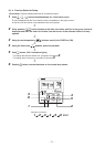
Step 2 Every time when the
UNIT LOUVER
button is pushed, the indoor unit No. under the group control is displayed in
order. Specify the indoor unit No. to be replaced.
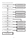
1. Change the CODE No. (DN) to
→ by pushing / buttons for the temperature
setting. (this is the setting for the filter sign lighting time.)
At this time, be sure to write down the setting data displayed.
2. Change the CODE No. (DN) by pushing
/ buttons for the temperature setting.
Similarly, be sure to write down the setting data displayed.
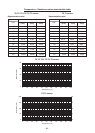
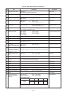
3. Repeat the step 2-2 to set the other settings in the same way and write down the setting data as shown
in the table 1 (example).
∗ The CODE No. (DN) are ranged from “
” to “..”. The CODE No. (DN) may skip.
Step 3 After writing down all setting data, push
TEST
button to return to the normal stop status.
(It takes approx. 1 min until the remote controller operation is available again.)
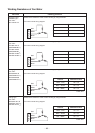
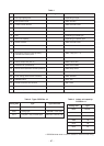
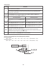
1. The CODE No. for the Indoor unit type and Indoor unit capacity are
required to set the rotation number setting of the fan.
2. If the system/indoor/group addresses are different from those before
replacement, the auto-address setting mode starts and the manual
resetting may be required again.
(when the multiple units group operation including twin, triple system.)
CODE No. required at least
DN
10
11
12
13
14
Contents
Type
Indoor unit capacity
System address
Indoor unit address
Group address