


– 79 –
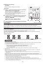
4. Wiring Specifications
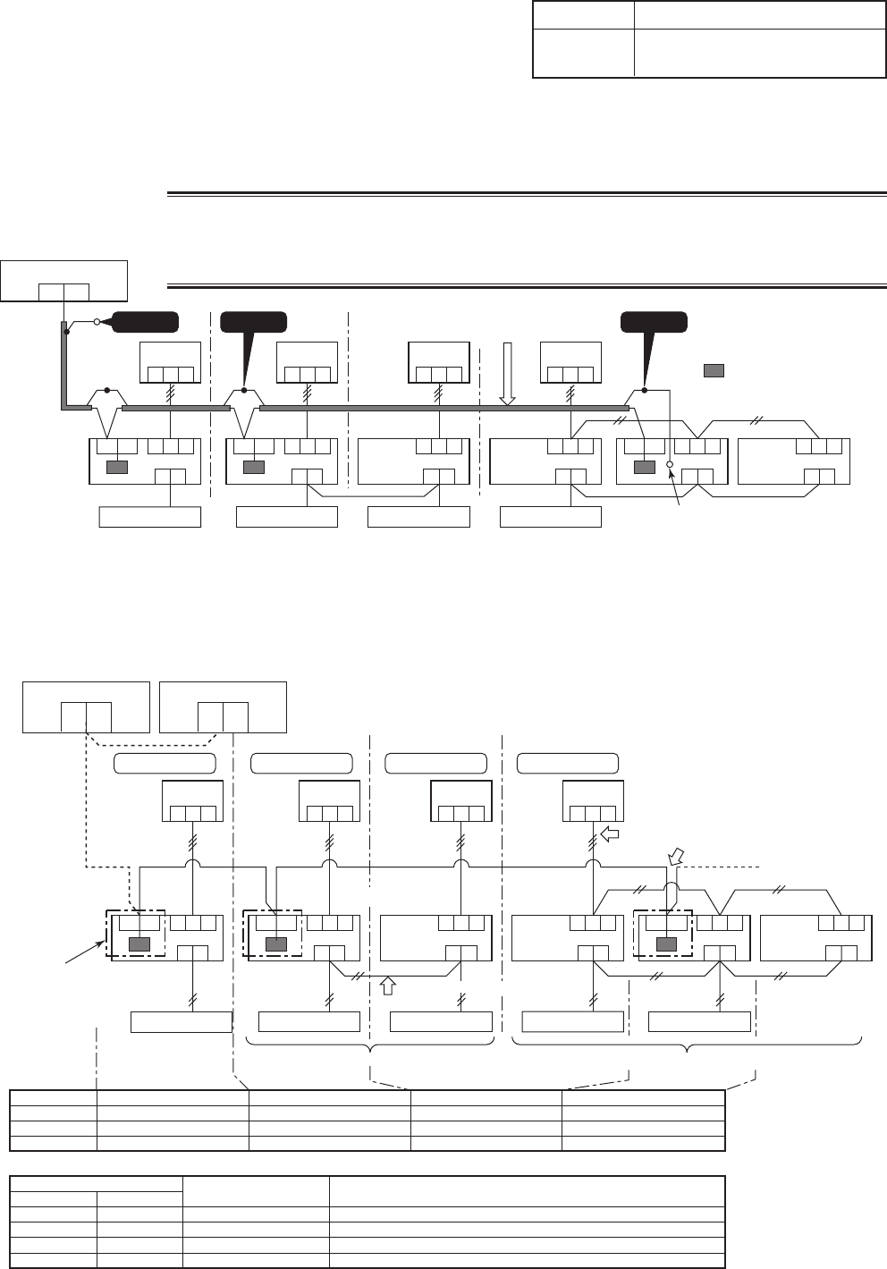
• Use 2-core with no polar wire.
• Match the length of wire to wire length of the central control
system. If mixed in the SMMS system, the wire length is
lengthened with all indoor/outdoor inter-unit wire length at side.
• To prevent noise trouble, use 2-core shield wire.
• Connect the shield wire by closed-end connection and apply open process (insulating process) to the last
terminal. Ground the earth wire to 1 point at indoor unit side. (In case of central controlling of digital inverter
(DI, SDI) unit setup)
CAUTION
1) Closed-end connection of shield wire (Connect all the connecting parts of each indoor unit)
2) Apply open process to the last terminal (insulating process).
3) Ground earth wire to 1 point at indoor unit side.
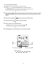
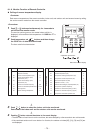
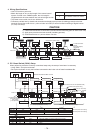
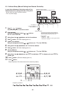
5. P.C. Board Switch (SW01) Setup
When performing collective control by customized setup only, the setup of terminator is necessary.
• Using SW01, set up the terminator.
• Set up the terminator to only the interface connected to the indoor unit of least line address No.
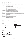
No. of wires
2
Size
Up to 1000m: twisted wire 1.25mm
2
Up to 2000m: twisted wire 2.0mm
2
Central control device
U1
U2
123
Outdoor unit
Indoor unit
12
3123123
123
A
B
U3
U4 123
A
B
U3
U4 123
A
B
123
A B
123
A B
123
A B
U3
U4
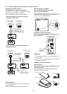
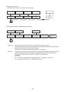
Caution 1
Remote controller
Central control system wiring
Header unit
Header unit
Follower unit
Follower unit
Follower unit
Caution 2
Remote controller Remote controller Remote controller
(Group operation) (Triple operation)
Caution 3
: 1:1 model connection
interface
(TCC-LINK adapter)
(This option)
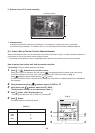
Earth screw
Central control device
U1
U3
U2
U4
Central control device
U1
U3
123
U2
U4
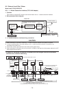
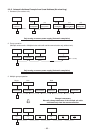
Central control devices: Max. 10 units
Refrigerant line 1
Outdoor unit
Indoor unit
12
3
Refrigerant line 2
12
3
Refrigerant line 3
12
3
Refrigerant line 4
123
A
B
U3
U4 123
A
B
U3
U4 123
A
B
123
A B
123
A B
123
A B
U3 U4
1:1 model connection interface
(TCC-LINK adapter)
This product
sold separately
( )
Remote controller
Indoor/outdoor inter-unit wire (AC230V serial)
Central control system wiring
Header
unit
Header unit
Followerunit
Follower unit
Follower
unit
* Wiring for No.1 and 2 only
Remote controller Remote controller Remote controller Remote controller
Remote controller wiring
Group operation (Max. 8 units) Twin/Triple operation (Example of triple)
(OFF at shipment from factory)
(OFF at shipment from factory)
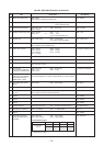
Line address
SW01 Bit 1
SW01 Bit 2
Remarks
1
ON
OFF
Turn SW01 Bit 1 to ON.
2
OFF
OFF
As status shipped from factory
4
OFF
OFF
As status shipped from factory
(Reference) Setup contents of switch
SW01
Bit 1
OFF
ON
OFF
ON
Bit 1
OFF
OFF
ON
ON
Terminator
None
100Ω
75Ω
43Ω
Remarks
Mixed with SMMS (Link wiring) at shipment from factory
Central control by digital inverter only
Spare
Spare